

ESD Failure on STUSB4500
Hey,
I am having a big issue with ESD discharges and the STUSB4500. Essentially, I auto negotiate to 20V, and on ESD discharge, the STUSB shuts off VBUS_EN_SINK, while the supply continues to supply 20V. My thought is that on ESD discharge, the chip for some reason thinks it has had a disconnect event, waits for the supply to recover to 5V, but the cable has not been disconnected so continues to supply VBUS with 20V, and the STUSB then is in a hard stuck state until actual unplug and re-plug. There is no error seen, as GPIO does not pull low and is configured to show error states.
I cannot find a document that exposes all of the register values, but after every shut down, the chip register state reads the same failure state. The dump is as below.
# Before discharge
STUSB4500 @ 0x28, registers 0x00..0xff
     00 01 02 03 04 05 06 07  08 09 0a 0b 0c 0d 0e 0f
00:  00 00 00 00 00 00 12 00  11 20 00 63 fb 01 41 0a
10:  0a 13 00 40 00 02 0c 2c  00 00 00 21 01 80 00 00
20:  10 c8 5f 00 00 9c 00 02  02 18 00 32 05 00 00 25
30:  00 66 05 51 2a 14 02 20  d1 02 00 2c c1 03 00 2c
40:  b1 04 00 45 41 06 00 e4  c9 aa 40 00 00 18 e3 00
50:  00 00 00 00 00 00 00 00  00 00 00 00 00 00 00 00
60:  00 00 00 00 00 00 00 00  00 00 00 00 00 00 00 00
70:  43 c8 90 01 08 64 d0 02  00 2c b1 04 00 f4 b1 04
80:  00 5e fd 01 00 96 90 01  10 96 b0 04 00 64 40 06
90:  00 45 91 01 50 00 40 00  00 00 00 00 00 00 00 00
a0:  00 00 00 00 00 00 00 00  00 00 00 00 00 00 00 00
b0:  00 00 00 00 00 00 00 00  00 00 00 00 00 00 00 00
c0:  00 00 00 00 00 00 00 00  00 00 00 00 00 00 00 00
d0:  00 00 00 00 00 00 00 00  00 00 00 00 00 00 00 00
e0:  00 00 00 00 00 00 00 00  00 00 00 00 00 00 00 00
f0:  00 00 00 00 00 00 00 00  00 00 00 00 00 00 00 00

# After discharge
STUSB4500 @ 0x28, registers 0x00..0xff
     00 01 02 03 04 05 06 07  08 09 0a 0b 0c 0d 0e 0f
00:  00 00 00 00 00 00 12 00  11 20 00 20 fb 00 00 02
10:  02 20 00 40 00 01 00 00  00 00 00 21 01 80 00 00
20:  10 32 af 00 00 9c 00 00  02 00 00 10 05 00 00 25
30:  00 00 00 00 00 00 00 00  00 00 00 00 00 00 00 00
40:  00 00 00 00 00 00 00 00  00 00 00 00 00 00 00 00
50:  00 00 00 00 00 00 00 00  00 00 00 00 00 00 00 00
60:  00 00 00 00 00 00 00 00  00 00 00 00 00 00 00 00
70:  43 c8 90 01 08 64 d0 02  00 2c b1 04 00 f4 b1 04
80:  00 5e fd 01 00 96 90 01  10 96 b0 04 00 64 40 06
90:  00 00 00 00 00 00 40 00  00 00 00 00 00 00 00 00
a0:  00 00 00 00 00 00 00 00  00 00 00 00 00 00 00 00
b0:  00 00 00 00 00 00 00 00  00 00 00 00 00 00 00 00
c0:  00 00 00 00 00 00 00 00  00 00 00 00 00 00 00 00
d0:  00 00 00 00 00 00 00 00  00 00 00 00 00 00 00 00
e0:  00 00 00 00 00 00 00 00  00 00 00 00 00 00 00 00
f0:  00 00 00 00 00 00 00 00  00 00 00 00 00 00 00 00
The schematic almost follows the reference design to a tee with a single stage turn-on. I have swapped R17 and R24 with 1ks, and have also tested a reworked version of my board with the actual reference design filtering on VBUS_VS_DISCH (shown in the image below the schematic). The issues manifest on all reworks the same way.
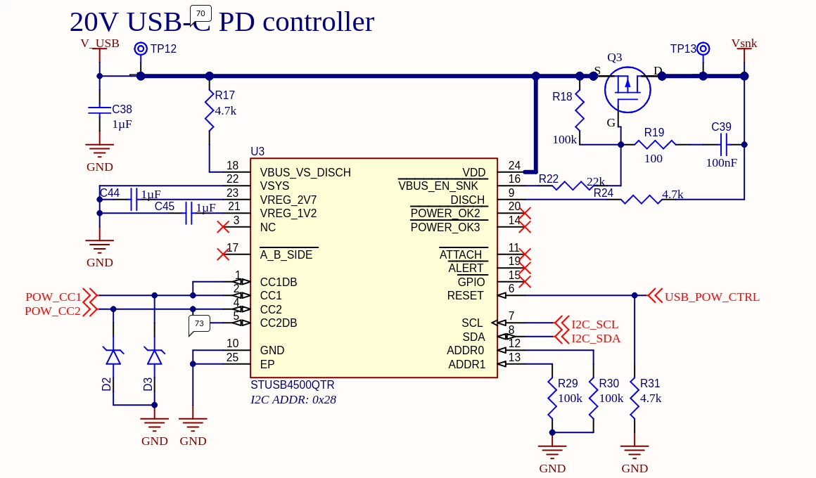

Some advice would be very much appreciated. I know that it possibly has to do with routing, so I can supply some routing snippets if needed, but some help thinking about the setup of this chip a little better, or some insight on register value meaning, would help a lot. If there is a register I am missing or something hardware wise in the schematic you could see causing issues, please let me know.