Associate
July 1, 2026
Solved

About the control connector of IPMM15B

  • July 1, 2026
  • 1 reply
  • 22 views

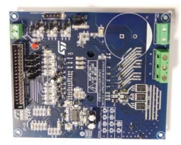
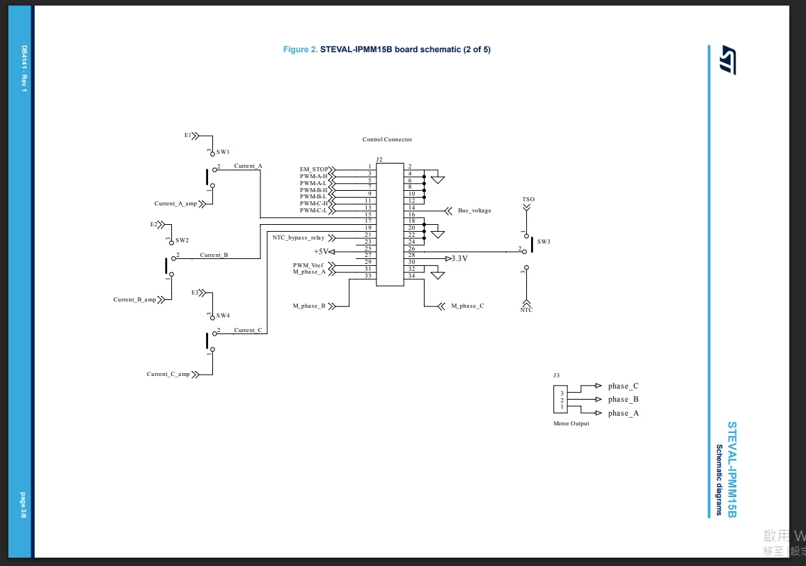
I am connecting IPMM15B’s J2 to IHM09M2's J7. There are  documents showing how J7 is aligned and where it is situated on the board. But I have no idea how J2 is oriented. The schematic is too brief. It could be opposite aligned if I turned the board around to the inverse side. I don’t know how the pins should be connected.


I need to know where pin1 pin2 is situated on the board.


Best answer by Peter BENSCH

Welcome ​@TyrantRenre, to the community!

You can find this information on the product website of the STEVAL-IPMM15B, for example, in UM2704, fig. 17, or by taking a look at the GERBER data. Since the connector has a notch to prevent reverse polarity, the corresponding 34-pin plug on a ribbon cable usually fits.

Hope that answers your question?

Regards
/Peter

1 reply

Associate
July 1, 2026
Peter BENSCH
Peter BENSCHBest answer
ST Technical Moderator
July 1, 2026

Welcome ​@TyrantRenre, to the community!

You can find this information on the product website of the STEVAL-IPMM15B, for example, in UM2704, fig. 17, or by taking a look at the GERBER data. Since the connector has a notch to prevent reverse polarity, the corresponding 34-pin plug on a ribbon cable usually fits.

Hope that answers your question?

Regards
/Peter

In order to give better visibility on the answered topics, please click on Accept as Solution on the reply which solved your issue or answered your question.
Associate
July 2, 2026

Thank you very much !

I have solved the problem from Figure 17.!