Associate
October 20, 2026
Question

NUCLEO-F410RB: LED display multiplexing

Hello all,

I’m building a prototype of simple digital clock that shows the current time in 24 hour format with 29 LEDs. The schematic also shows a 10-LED bar, but it is not implemented at the moment. The LEDs are divided into four banks: minutes, tens of minutes, hours and tens of hours. LED cathodes are controlled via two 8-bit shift registers driven via SPI2 & two GPIO pins.

I’m prototyping with a Nucleo-F410RB board which uses the STM32F410 chip. I’m using the STM32Cube and STM32CubeIDE for development.

I would like to know if it’s possible/feasible to use a 4-channel timer (such as TIM1) in PWM mode for driving the four multiplex signals (MPX0..3 in the schematic below)? Or is GPIO pins with software control the best choice for this application?

Thank you for your advice!
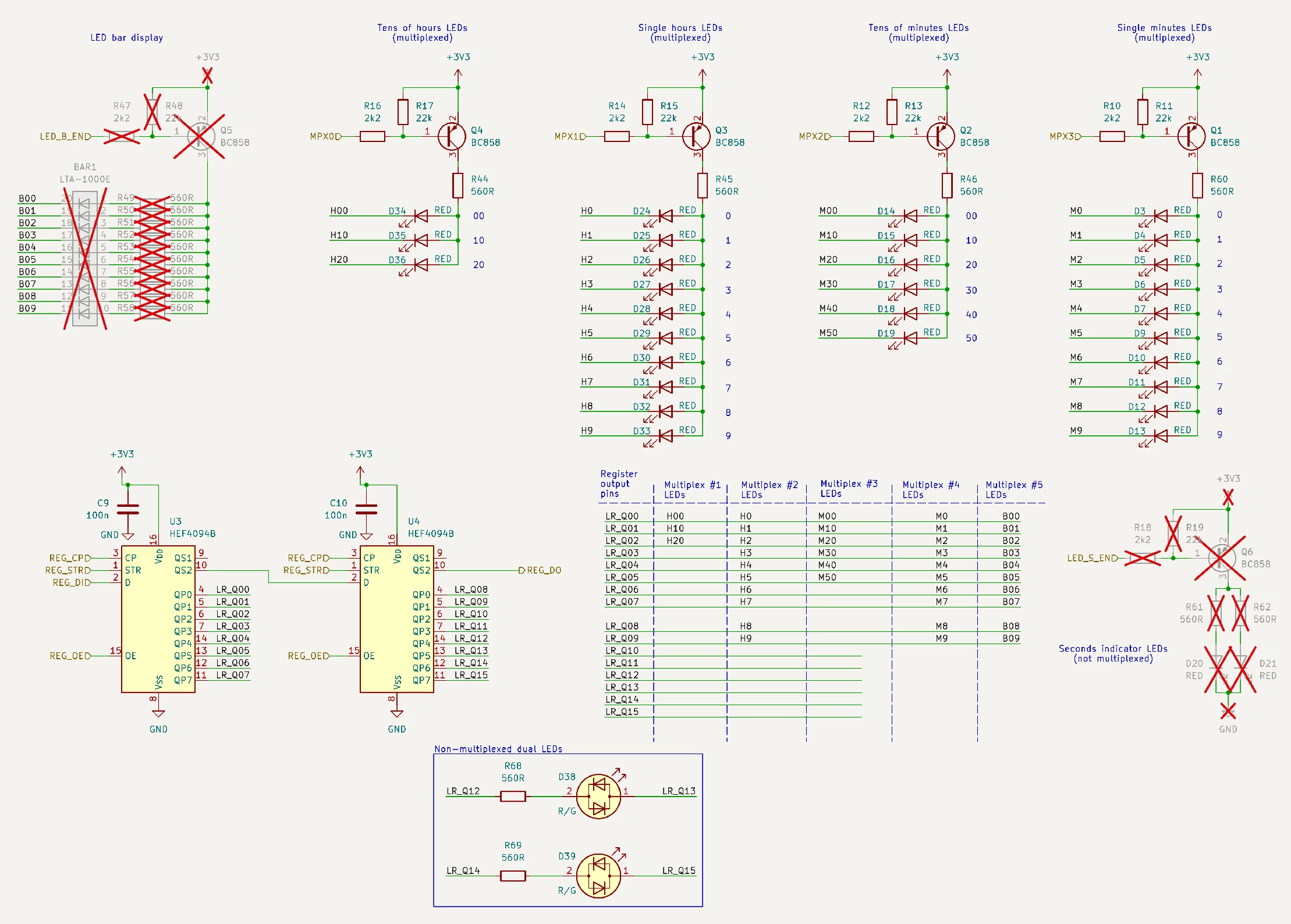
LED display schematic
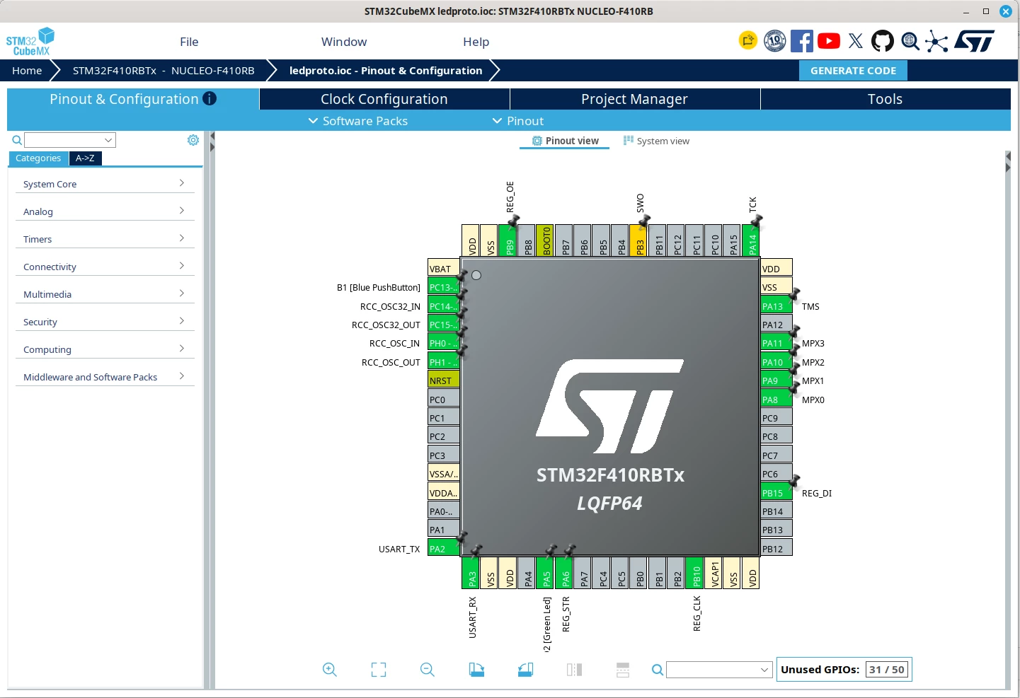
STM32 I/O pins
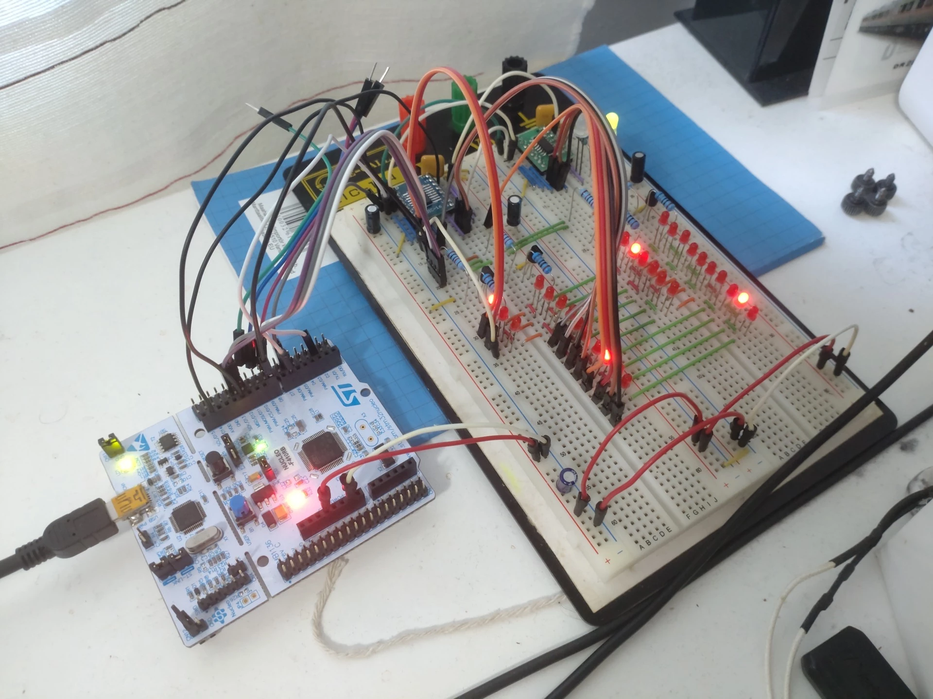
My messy prototype setup showing the time “07:18” and one bi-LED showing the status “green”.


2 replies

gbm
Super User
October 21, 2026

First, what you’ve created is not really a typical multiplexed display. Only one of matrix LEDs is active at a time, so the transistors are not needed at all. When configured as a crossplexed matrix, the display would require 6 GPIO outputs and 6 resistors with no shift registers.

Second, no, you cannot use hardware control of four timer outputs. This is not really a problem, cause you must use a software routine called from fixed frequency timer interrupt for SPI control anyway, and software control of anodes adds just two lines of code to that routine.

My STM32 stuff on github - compact USB device stack and more: https://github.com/gbm-ii/gbmUSBdevice
artrasaAuthor
Associate
October 22, 2026

Thank you for your help. Removing the registers and transistors certainly makes the circuit simpler.

Currently I am using TIM5 to generate interrupts at 1000 Hz. This is used for activating the LED anodes sequentially.

I was wondering if TIM1 one-pulse mode could be used for driving the LED anodes? Image upload does not seem to work, but AN4776 timer cookbook pg. 36-37 shows an example of one-pulse mode. If I kept the pulse length less than 1ms in length, wouldn’t it be possible to start TIM1 in one-pulse mode at the beginning of each multiplexing cycle to turn on the corresponding LED display?