Question
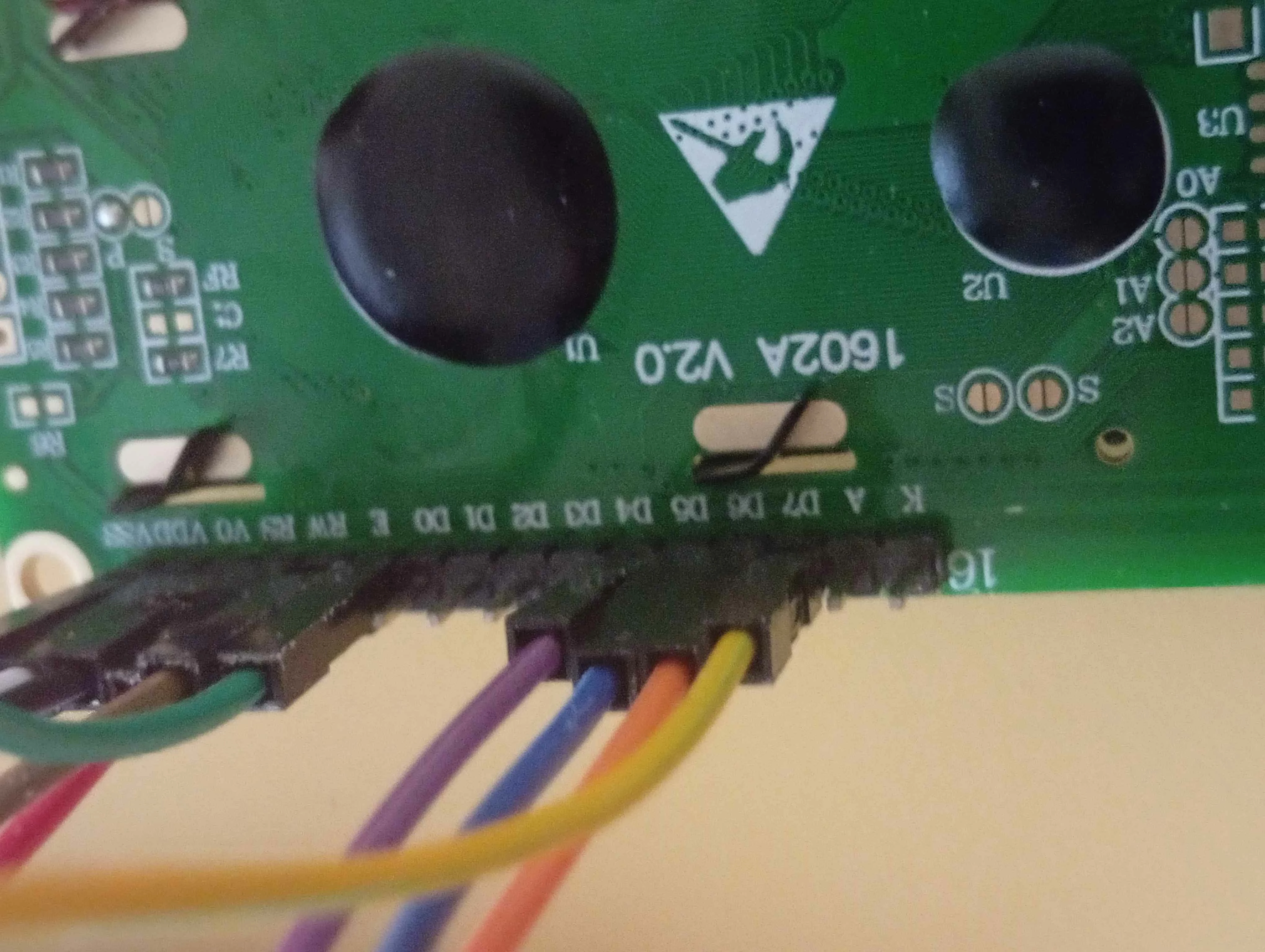
Connection to alphanumeric LCD model 1602
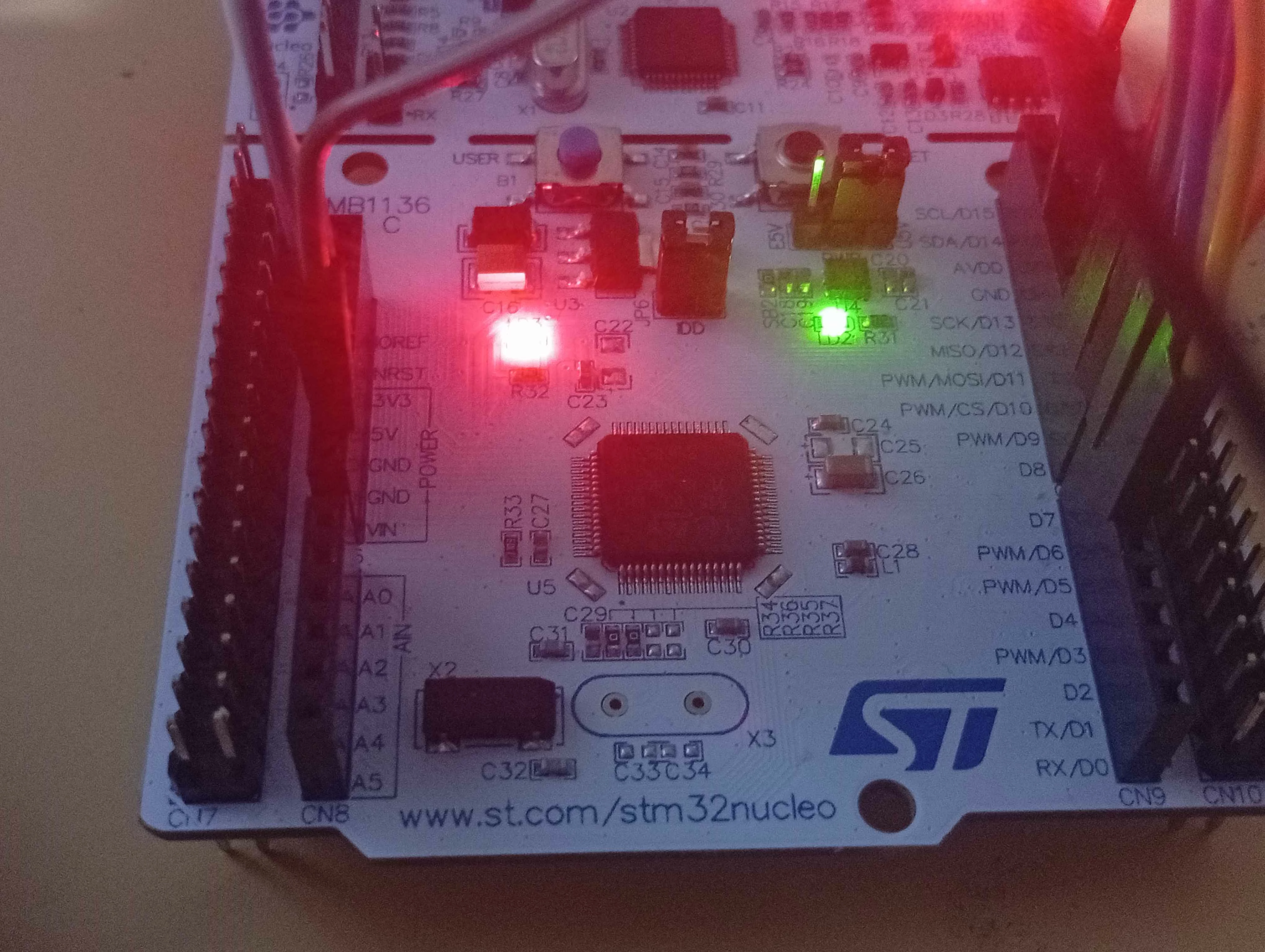
Hello. I am a beginner, I am trying to connect an STM32 nucleo f446re to an LCD, model 1602A V 2.0.
I tried making a test code with no functions to see if the display works
I only see a grid of rectangles light up and when running the code no characters display. What could be the issue?
This is the code:
int main(void){


/* USER CODE BEGIN 1 */


HAL_Init();

SystemClock_Config();


// LCD Board label STM32 pin

//---------------------------------------

// RS D10 PB6

// E D9 PC7

// D4 D8 PA9

// D5 D7 PA8

// D6 D6 PB10

// D7 D5 PB4


// =====================================================

// ENABLE GPIO CLOCKS

// =====================================================


RCC->AHB1ENR |= RCC_AHB1ENR_GPIOAEN;

RCC->AHB1ENR |= RCC_AHB1ENR_GPIOBEN;

RCC->AHB1ENR |= RCC_AHB1ENR_GPIOCEN;


// =====================================================

// CONFIGURE GPIO PINS AS OUTPUTS

// =====================================================


// PB6 = RS

GPIOB->MODER &= ~(3U << (6 * 2));

GPIOB->MODER |= (1U << (6 * 2));


// PC7 = E

GPIOC->MODER &= ~(3U << (7 * 2));

GPIOC->MODER |= (1U << (7 * 2));


// PA9 = D4

GPIOA->MODER &= ~(3U << (9 * 2));

GPIOA->MODER |= (1U << (9 * 2));


// PA8 = D5

GPIOA->MODER &= ~(3U << (8 * 2));

GPIOA->MODER |= (1U << (8 * 2));


// PB10 = D6

GPIOB->MODER &= ~(3U << (10 * 2));

GPIOB->MODER |= (1U << (10 * 2));


// PB4 = D7

GPIOB->MODER &= ~(3U << (4 * 2));

GPIOB->MODER |= (1U << (4 * 2));


// =====================================================

// LCD POWER-UP WAIT

// =====================================================


HAL_Delay(20);


// =====================================================

// 4-BIT INITIALIZATION

// =====================================================


// RS = 0

// Command mode

GPIOB->BSRR = (1U << (6 + 16));


// =====================================================

// SEND 0011

// =====================================================


// D7 = 0

GPIOB->BSRR = (1U << (4 + 16));


// D6 = 0

GPIOB->BSRR = (1U << (10 + 16));


// D5 = 1

GPIOA->BSRR = (1U << 8);


// D4 = 1

GPIOA->BSRR = (1U << 9);


// Pulse E

GPIOC->BSRR = (1U << 7);

HAL_Delay(1);

GPIOC->BSRR = (1U << (7 + 16));


HAL_Delay(5);


// =====================================================

// SEND 0011 AGAIN

// =====================================================


// D7 = 0

GPIOB->BSRR = (1U << (4 + 16));


// D6 = 0

GPIOB->BSRR = (1U << (10 + 16));


// D5 = 1

GPIOA->BSRR = (1U << 8);


// D4 = 1

GPIOA->BSRR = (1U << 9);


// Pulse E

GPIOC->BSRR = (1U << 7);

HAL_Delay(1);

GPIOC->BSRR = (1U << (7 + 16));


HAL_Delay(1);


// =====================================================

// SEND 0011 A THIRD TIME

// =====================================================


// D7 = 0

GPIOB->BSRR = (1U << (4 + 16));


// D6 = 0

GPIOB->BSRR = (1U << (10 + 16));


// D5 = 1

GPIOA->BSRR = (1U << 8);


// D4 = 1

GPIOA->BSRR = (1U << 9);


// Pulse E

GPIOC->BSRR = (1U << 7);

HAL_Delay(1);

GPIOC->BSRR = (1U << (7 + 16));


HAL_Delay(1);


// =====================================================

// SEND 0010

// Switch LCD to 4-bit mode

// =====================================================


// D7 = 0

GPIOB->BSRR = (1U << (4 + 16));


// D6 = 0

GPIOB->BSRR = (1U << (10 + 16));


// D5 = 1

GPIOA->BSRR = (1U << 8);


// D4 = 0

GPIOA->BSRR = (1U << (9 + 16));


// Pulse E

GPIOC->BSRR = (1U << 7);

HAL_Delay(1);

GPIOC->BSRR = (1U << (7 + 16));


HAL_Delay(1);


// =====================================================

// LCD IS NOW IN 4-BIT MODE

// =====================================================


// =====================================================

// COMMAND: 0x28

// 0010 1000

//

// 4-bit mode

// 2 lines

// 5x8 character font

// =====================================================


// RS = 0

GPIOB->BSRR = (1U << (6 + 16));


// First nibble = 0010


// D7 = 0

GPIOB->BSRR = (1U << (4 + 16));


// D6 = 0

GPIOB->BSRR = (1U << (10 + 16));


// D5 = 1

GPIOA->BSRR = (1U << 8);


// D4 = 0

GPIOA->BSRR = (1U << (9 + 16));


// E pulse

GPIOC->BSRR = (1U << 7);

HAL_Delay(1);

GPIOC->BSRR = (1U << (7 + 16));


// Second nibble = 1000


// D7 = 1

GPIOB->BSRR = (1U << 4);


// D6 = 0

GPIOB->BSRR = (1U << (10 + 16));


// D5 = 0

GPIOA->BSRR = (1U << (8 + 16));


// D4 = 0

GPIOA->BSRR = (1U << (9 + 16));


// E pulse

GPIOC->BSRR = (1U << 7);

HAL_Delay(1);

GPIOC->BSRR = (1U << (7 + 16));


// =====================================================

// COMMAND: 0x0C

// 0000 1100

//

// Display ON

// Cursor OFF

// Blink OFF

// =====================================================


// RS = 0

GPIOB->BSRR = (1U << (6 + 16));


// First nibble = 0000


// D7 = 0

GPIOB->BSRR = (1U << (4 + 16));


// D6 = 0

GPIOB->BSRR = (1U << (10 + 16));


// D5 = 0

GPIOA->BSRR = (1U << (8 + 16));


// D4 = 0

GPIOA->BSRR = (1U << (9 + 16));


// E pulse

GPIOC->BSRR = (1U << 7);

HAL_Delay(1);

GPIOC->BSRR = (1U << (7 + 16));


// Second nibble = 1100


// D7 = 1

GPIOB->BSRR = (1U << 4);


// D6 = 1

GPIOB->BSRR = (1U << 10);


// D5 = 0

GPIOA->BSRR = (1U << (8 + 16));


// D4 = 0

GPIOA->BSRR = (1U << (9 + 16));


// E pulse

GPIOC->BSRR = (1U << 7);

HAL_Delay(1);

GPIOC->BSRR = (1U << (7 + 16));


// =====================================================

// COMMAND: 0x01

// 0000 0001

//

// Clear display

// =====================================================


// RS = 0

GPIOB->BSRR = (1U << (6 + 16));


// First nibble = 0000


// D7 = 0

GPIOB->BSRR = (1U << (4 + 16));


// D6 = 0

GPIOB->BSRR = (1U << (10 + 16));


// D5 = 0

GPIOA->BSRR = (1U << (8 + 16));


// D4 = 0

GPIOA->BSRR = (1U << (9 + 16));


// E pulse

GPIOC->BSRR = (1U << 7);

HAL_Delay(1);

GPIOC->BSRR = (1U << (7 + 16));


// Second nibble = 0001


// D7 = 0

GPIOB->BSRR = (1U << (4 + 16));


// D6 = 0

GPIOB->BSRR = (1U << (10 + 16));


// D5 = 0

GPIOA->BSRR = (1U << (8 + 16));


// D4 = 1

GPIOA->BSRR = (1U << 9);


// E pulse

GPIOC->BSRR = (1U << 7);

HAL_Delay(1);

GPIOC->BSRR = (1U << (7 + 16));


// Clear display takes longer than normal commands

HAL_Delay(5);


// =====================================================

// COMMAND: 0x06

// 0000 0110

//

// Increment cursor after each character

// =====================================================


// RS = 0

GPIOB->BSRR = (1U << (6 + 16));


// First nibble = 0000


// D7 = 0

GPIOB->BSRR = (1U << (4 + 16));


// D6 = 0

GPIOB->BSRR = (1U << (10 + 16));


// D5 = 0

GPIOA->BSRR = (1U << (8 + 16));


// D4 = 0

GPIOA->BSRR = (1U << (9 + 16));


// E pulse

GPIOC->BSRR = (1U << 7);

HAL_Delay(1);

GPIOC->BSRR = (1U << (7 + 16));


// Second nibble = 0110


// D7 = 0

GPIOB->BSRR = (1U << (4 + 16));


// D6 = 1

GPIOB->BSRR = (1U << 10);


// D5 = 1

GPIOA->BSRR = (1U << 8);


// D4 = 0

GPIOA->BSRR = (1U << (9 + 16));


// E pulse

GPIOC->BSRR = (1U << 7);

HAL_Delay(1);

GPIOC->BSRR = (1U << (7 + 16));


// =====================================================

// SEND "hello"

// =====================================================


// RS = 1 → data mode

GPIOB->BSRR = (1U << 6);


// =====================================================

// 'h' = 0x68 = 0110 1000

// =====================================================


// Upper nibble = 0110


// D7 = 0

GPIOB->BSRR = (1U << (4 + 16));


// D6 = 1

GPIOB->BSRR = (1U << 10);


// D5 = 1

GPIOA->BSRR = (1U << 8);


// D4 = 0

GPIOA->BSRR = (1U << (9 + 16));


// E pulse

GPIOC->BSRR = (1U << 7);

HAL_Delay(1);

GPIOC->BSRR = (1U << (7 + 16));


// Lower nibble = 1000


// D7 = 1

GPIOB->BSRR = (1U << 4);


// D6 = 0

GPIOB->BSRR = (1U << (10 + 16));


// D5 = 0

GPIOA->BSRR = (1U << (8 + 16));


// D4 = 0

GPIOA->BSRR = (1U << (9 + 16));


// E pulse

GPIOC->BSRR = (1U << 7);

HAL_Delay(1);

GPIOC->BSRR = (1U << (7 + 16));


// =====================================================

// 'e' = 0x65 = 0110 0101

// =====================================================


// Upper nibble = 0110


// D7 = 0

GPIOB->BSRR = (1U << (4 + 16));


// D6 = 1

GPIOB->BSRR = (1U << 10);


// D5 = 1

GPIOA->BSRR = (1U << 8);


// D4 = 0

GPIOA->BSRR = (1U << (9 + 16));


// E pulse

GPIOC->BSRR = (1U << 7);

HAL_Delay(1);

GPIOC->BSRR = (1U << (7 + 16));


// Lower nibble = 0101


// D7 = 0

GPIOB->BSRR = (1U << (4 + 16));


// D6 = 1

GPIOB->BSRR = (1U << 10);


// D5 = 0

GPIOA->BSRR = (1U << (8 + 16));


// D4 = 1

GPIOA->BSRR = (1U << 9);


// E pulse

GPIOC->BSRR = (1U << 7);

HAL_Delay(1);

GPIOC->BSRR = (1U << (7 + 16));


// =====================================================

// 'l' = 0x6C = 0110 1100

// =====================================================


// Upper nibble = 0110


// D7 = 0

GPIOB->BSRR = (1U << (4 + 16));


// D6 = 1

GPIOB->BSRR = (1U << 10);


// D5 = 1

GPIOA->BSRR = (1U << 8);


// D4 = 0

GPIOA->BSRR = (1U << (9 + 16));


// E pulse

GPIOC->BSRR = (1U << 7);

HAL_Delay(1);

GPIOC->BSRR = (1U << (7 + 16));


// Lower nibble = 1100


// D7 = 1

GPIOB->BSRR = (1U << 4);


// D6 = 1

GPIOB->BSRR = (1U << 10);


// D5 = 0

GPIOA->BSRR = (1U << (8 + 16));


// D4 = 0

GPIOA->BSRR = (1U << (9 + 16));


// E pulse

GPIOC->BSRR = (1U << 7);

HAL_Delay(1);

GPIOC->BSRR = (1U << (7 + 16));


// =====================================================

// Second 'l' = 0x6C = 0110 1100

// =====================================================


// Upper nibble = 0110


// D7 = 0

GPIOB->BSRR = (1U << (4 + 16));


// D6 = 1

GPIOB->BSRR = (1U << 10);


// D5 = 1

GPIOA->BSRR = (1U << 8);


// D4 = 0

GPIOA->BSRR = (1U << (9 + 16));


// E pulse

GPIOC->BSRR = (1U << 7);

HAL_Delay(1);

GPIOC->BSRR = (1U << (7 + 16));


// Lower nibble = 1100


// D7 = 1

GPIOB->BSRR = (1U << 4);


// D6 = 1

GPIOB->BSRR = (1U << 10);


// D5 = 0

GPIOA->BSRR = (1U << (8 + 16));


// D4 = 0

GPIOA->BSRR = (1U << (9 + 16));


// E pulse

GPIOC->BSRR = (1U << 7);

HAL_Delay(1);

GPIOC->BSRR = (1U << (7 + 16));


// =====================================================

// 'o' = 0x6F = 0110 1111

// =====================================================


// Upper nibble = 0110


// D7 = 0

GPIOB->BSRR = (1U << (4 + 16));


// D6 = 1

GPIOB->BSRR = (1U << 10);


// D5 = 1

GPIOA->BSRR = (1U << 8);


// D4 = 0

GPIOA->BSRR = (1U << (9 + 16));


// E pulse

GPIOC->BSRR = (1U << 7);

HAL_Delay(1);

GPIOC->BSRR = (1U << (7 + 16));


// Lower nibble = 1111


// D7 = 1

GPIOB->BSRR = (1U << 4);


// D6 = 1

GPIOB->BSRR = (1U << 10);


// D5 = 1

GPIOA->BSRR = (1U << 8);


// D4 = 1

GPIOA->BSRR = (1U << 9);


// E pulse

GPIOC->BSRR = (1U << 7);

HAL_Delay(1);

GPIOC->BSRR = (1U << (7 + 16));


// =====================================================

// MAIN LOOP

// =====================================================


while (1)

{

}


/* USER CODE END 1 */


}