
Associate
August 22, 2026
Solved

20ns Pulses on MISO Line when Slave is not Programmed to Transmit

  • August 22, 2026
  • 4 replies
  • 21 views

Hi, 

I am using two STM23F303 Discovery Borads.

My application is as follows:

The two boards communicate via SPI.

Every two seconds the master boards send a uint8 message to the slave.

Upon receiving the message, the slave board shall light up some LEDs depending on the sent message.

This is a snippet of the code flashed to the slave board:

while (FOREVER)
{
// When you receive a message from
if (HAL_SPI_Receive(&hspi1, &u8SpiMsg, U16_NUM_BYTES, HAL_MAX_DELAY) == HAL_OK)
{
// Set/Reset corresponding LED pins via their control bits in BSRR register
GPIOE->BSRR = ...........;
}
}

This is the configuration of the SPI: 

Mode - Full-Duplex Master/Slave
Hardware NSS Signal - Hardware NSS Input Signal
Frame Format - Motorola
Data Size - 8 bit
First Bit - MSB First
Prescaler (for Baud Rate) - 8
Clock Polarity - low
Clock Phase - 1 Edge
CRC Calculation - disable
NSSP Mode - Disable

The application works, but when I hooked up a logic analyser (saleae logic to inspect the SPI communication, I saw that the MISO line is not always idle.

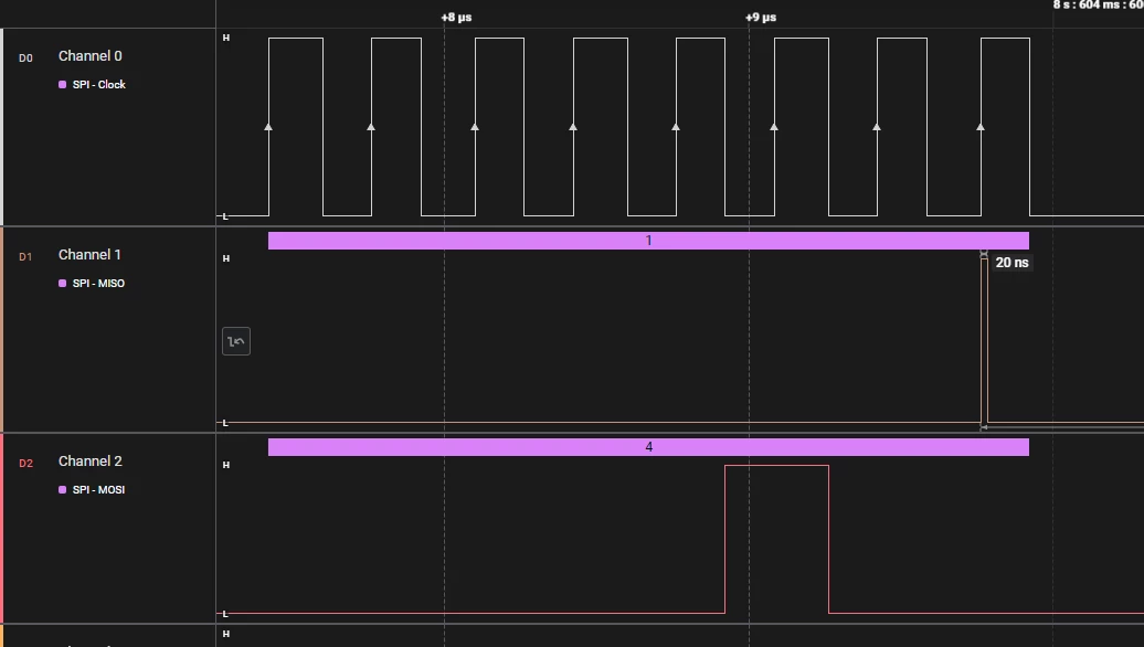
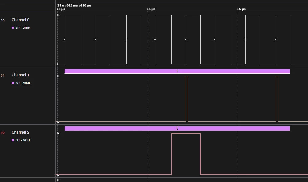
Some pulses of 20ns are observed on the MISO line whenever the slave sends a message, as shown in the following screenshots:
46c5cb85-b066-ca06-64e8-7a30c5bc899a.png6d035316-7301-1b79-04d3-4885236ce928.png


I don't understand why the MISO isn't idle when the slave is not sending anything? What is causing the 20ns pulses ?

Best answer by AScha.3

Hi,

probably you see just an artifact from capacitive coupling clk -> miso , as your "spike" is exactly at the rising edge of the clock.

So have better isolation of the lines to reduce the crosstalk .

+

And use a high speed scope to see the real crosstalk/pulses - if you like .

A simple logic analyzer connected with unscreened signal wires is not useful for assessing conduction/crosstalk effects.

4 replies

AScha.3
AScha.3Best answer
Super User
August 22, 2026

Hi,

probably you see just an artifact from capacitive coupling clk -> miso , as your "spike" is exactly at the rising edge of the clock.

So have better isolation of the lines to reduce the crosstalk .

+

And use a high speed scope to see the real crosstalk/pulses - if you like .

A simple logic analyzer connected with unscreened signal wires is not useful for assessing conduction/crosstalk effects.

If you feel a post has answered your question, please click on " Best Answer ".
Andrew Neil
Super User
August 22, 2026

@AScha.3  wrote:

se a high speed scope to see the real crosstalk/pulses.


Absolutely!

@melek_g  you always need to use a 'scope first to confirm that the signal is good & clean.

If the signal is not clean, a logic analyser will give misleading results ...


#ScopeFirst #ScopeThenLogicAnalyser

A complex system that works is invariably found to have evolved from a simple system that worked.A complex system designed from scratch never works and cannot be patched up to make it work.
melek_gAuthor
Associate
August 22, 2026

Unfortunately, I don't have a scope in the lab yet.

But thanks a lot for the advice. I'll definitely do that when I get one!