MSAMB.1
Associate III
September 8, 2020
Solved

VL6180X INTERRUPT TO GPIO1

  • September 8, 2020
  • 8 replies
  • 2811 views

Hello,

I am using a PNUCLEO VL6180X and I would like to drive my LED from the GPIO1 interrupt output only this output as shown in the diagrams above is always at 1 and it goes to 0 only for a few nanoseconds; I would like to have an interrupt signal only when I bring my hand closer to the sensor, I would like it to send a 1 to the LED when there is a target and a 0 when there is nothing.

Here are some images on the oscilloscope with the target and without the target
This topic has been closed for replies.
Best answer by MSAMB.1

0693W000004GLIYQA4.png0693W000004GLIJQA4.pngHello @Eleon BORLINI​ 

Yes I've found the solution thanks evryone for helping me.

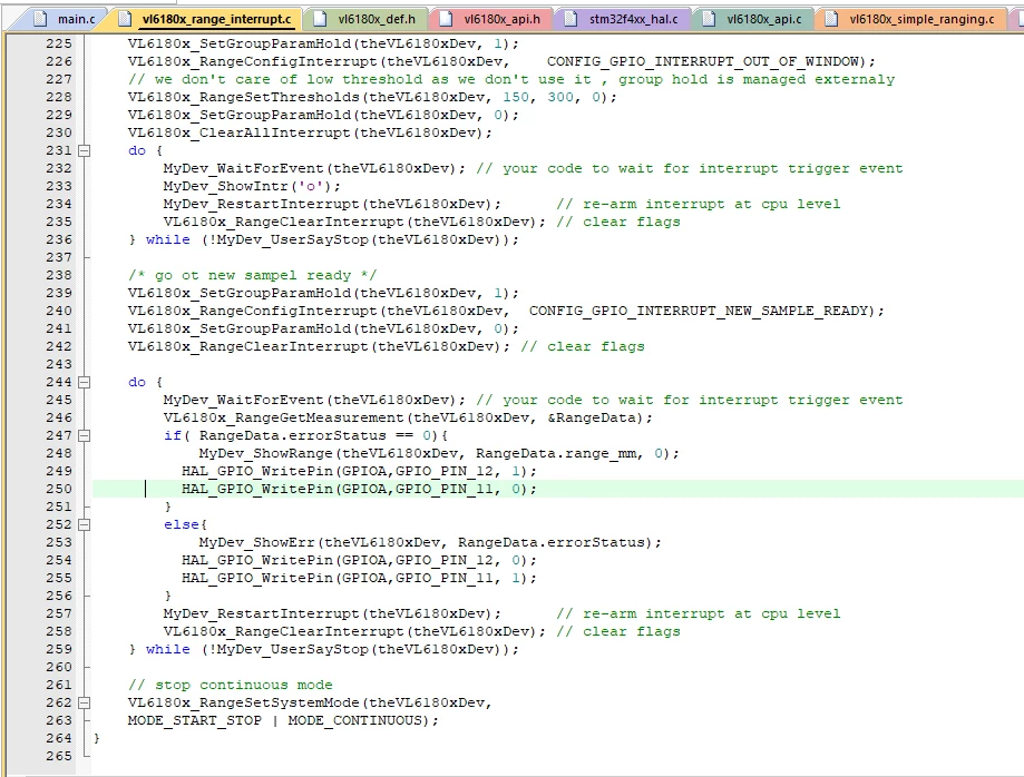
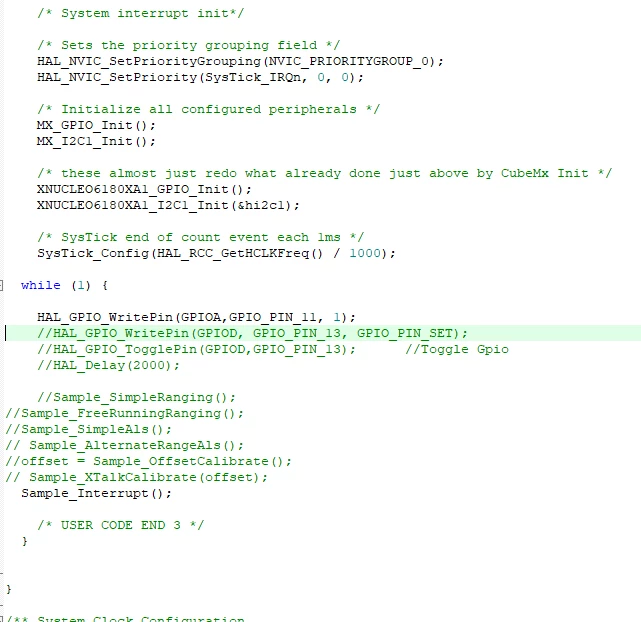
I sent you an example of my main code and my interrupt code. I've just take another pin of the MCU to command the LED it was very simple when my MCU detect the interruption my LED blink but I've add another LED who should take on when no target is detected and off when target is detected. Sorry for my english i'm french.

In the bottom you will see the code. Thank you

8 replies

Julien NGUYEN
ST Employee
September 8, 2020

Hi,

I m not sure that the GPIO1 has enough current to drive a LED. I think that it is better to connect the GPIO1 pin to a MCU GPIO to detect the event then from the MCU send a current to drive a LED ?

Thanks,

Julien

In order to give better visibility on the answered topics, please click on 'Accept as Solution' on the reply which solved your issue or answered your question.
MSAMB.1
MSAMB.1Author
Associate III
September 9, 2020

OK thank you Julien,

I've another questions :

In my main program, I'm calling the Sample_Ranging () functions to perform the measurement and the Sample_Interrupt () function to generate the interrupt but when I just call the sample_interrupt, I don't have a distance display in mm although with the new sample ready I have a show range.. How do you explain that ?

The other thing is if I want to add a new GPIO port from the mcu in which wait loop should I add the line of code to do it?

Thank you

Eleon BORLINI
ST Employee
September 17, 2020

Hi @MSAMB.1​ ,

my suggestion to you is to share at least a section of your code to get more help on this last question.

-Eleon

MSAMB.1
MSAMB.1AuthorBest answer
Associate III
September 17, 2020

0693W000004GLIYQA4.png0693W000004GLIJQA4.pngHello @Eleon BORLINI​ 

Yes I've found the solution thanks evryone for helping me.

I sent you an example of my main code and my interrupt code. I've just take another pin of the MCU to command the LED it was very simple when my MCU detect the interruption my LED blink but I've add another LED who should take on when no target is detected and off when target is detected. Sorry for my english i'm french.

In the bottom you will see the code. Thank you

Eleon BORLINI
ST Employee
September 17, 2020

Good job @MSAMB.1​ !

-Eleon

Julien NGUYEN
ST Employee
October 14, 2020

​Hi MSAMB, there is two calibrations . One is the offset calibration and the second one is the xtalk calibration.

You only need to do the calibration if you are looking for high precision measurement. If you only want to check if something/someone is present. You won't need.

If you add a cover glass (you called it protection support), depending on the cover glass (thickness, air-gap(distance between the sensor and the cover glass)) you may need to calibrate the cover glass. You may check out the application note DT0032 on st.com to learn how to calibrate the crosstalk I hope it helps. Thanks, Julien

In order to give better visibility on the answered topics, please click on 'Accept as Solution' on the reply which solved your issue or answered your question.