

Question about LSM6DSO PCB design
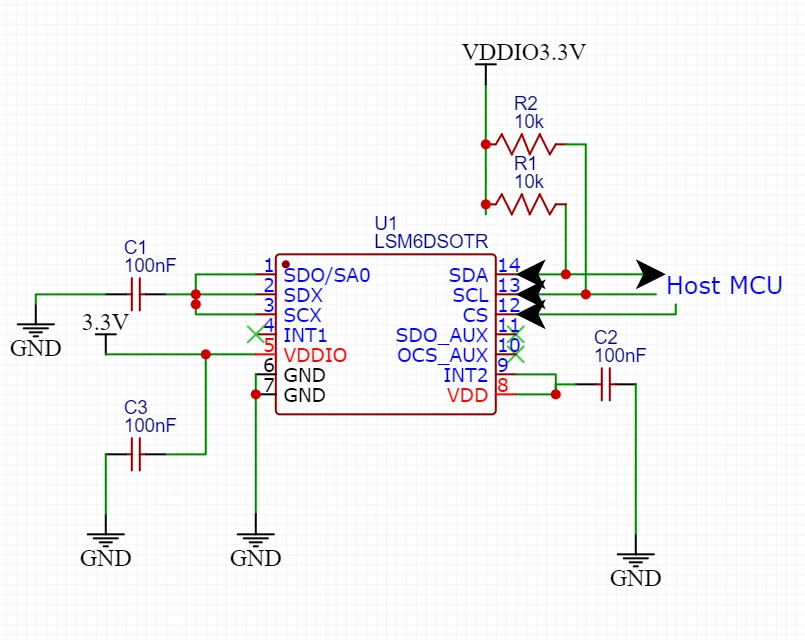
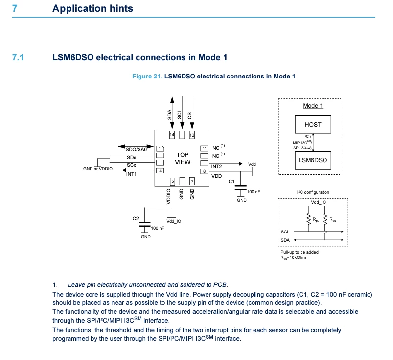 I'm currently trying to build a custom PCB using LSM6DSO. I just have few questions about the pins I don't use. I have no need for SPI communication, interrupts and VDD, not VDDIO cuz I need to power it through my RPi. I only need I2C communication and I need the PCB to be as small as it can get (like 1.6 cm in width, 2.4 cm in length), so I thought of connecting the unused pins, which are VDD, INT2, SCX, SDX, SDO/SA0 in this case to the ground with capacitors and only have the pins for I2C for soldering. The X's on the pins mean I should leave them unconnected.
My question is, are there any pins on the schematics I made that should not be connected to the ground and should rather leave them unconnected after making their pins? I am very much new to circuit. Any advice, recommendation or anything helpful is very welcome.