


kobelev
Associate
September 22, 2022
Solved

LSM9DS1 - how should I understand the fields of the CTRL_REG2_G (0x11) register

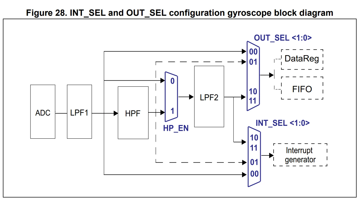
The datasheet on the LSM9DS1 chip on page 47 is very unclear on how the configuration of filters is supposed to work. They just tell that the fields INT_SEL and OUT_SEL are existing and give this diagram:
0693W00000SvxhZQAR.png 

I have hard time trying to understand what those dashed lines might mean. Why are they dashed? I understand that INT_SEL and OUT_SEL are similar. So, I give just one table below. I tend to decipher the situation this way:
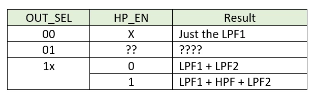
0693W00000SvxkAQAR.pngCan anybody comment if my guess is right and what should I put into the missing fields?
This topic has been closed for replies.
kobelev
kobelevBest answer
Associate
October 1, 2022

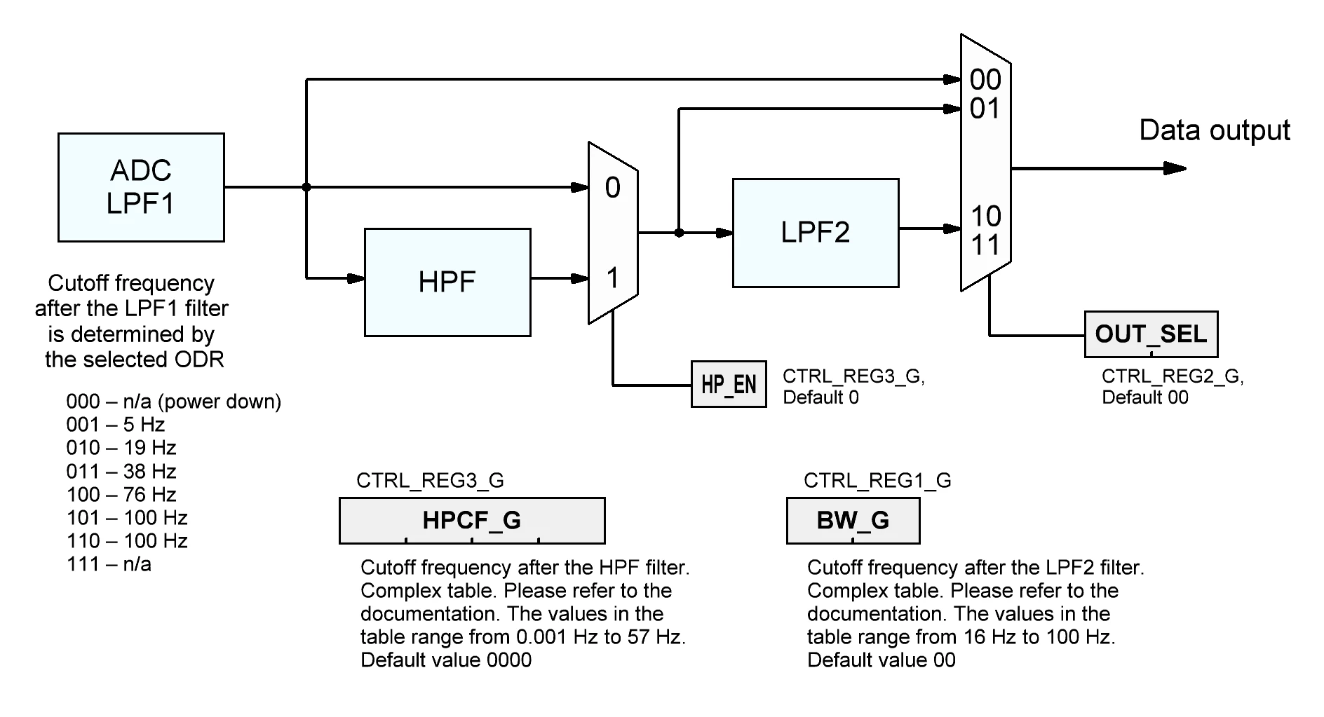
So, I would rewrite the picture above (just the data channel since the interrupts channel is similar) this way:

0693W00000Un9lOQAR.pngThe same in the table form:

0693W00000Un9lTQAR.png 

2 replies

Eleon BORLINI
ST Employee
September 30, 2022

Hi @kobelev​ ,

The table is ok, and when OUT_SEL == 01 is selected, if the HP_EN == 0 (CTRL_REG3_G (12h)), then the acquired signal will only pass through LPF1, while if HP_EN == 1 the resulting chain would be LPF1 + HPF.

-Eleon

kobelev
kobelevAuthorBest answer
Associate
October 1, 2022

So, I would rewrite the picture above (just the data channel since the interrupts channel is similar) this way:

0693W00000Un9lOQAR.pngThe same in the table form:

0693W00000Un9lTQAR.png
