
LSM6DSV16X Higher than expected current consumption
I have a LSM6DSV16X IMU powered from a 3.3V LDO. It communicates with a TMS320F2800137 MCU via SPI which is powered from a separate 3.3V buck rail. Power to the MCU and rest of system is controlled via the shutdown of the 3.3V buck. An interrupt from the IMU can control the shutdown of this 3.3V buck to wake it back up again.
My first issue arose when powering down the MCU system that 3.3 V from the IMU would back feed from the CS pin 12 through the GPIO of the MCU and draw excessive current as seen as a 0.6V drop across the 3.3V buck rail. Current measurements showed 700uA from the 14.4 V supply. To fix this backfeeding voltage I turned off the I2C/I3C interface via the IF_CFG register, however, this leads to the next issue.
With the IMU programmed with the accelerometer in LPM1 with ODR 1.875 Hz and gyroscope in sleep mode; no other embedded functions enabled, I disable power to the 3.3V buck, leaving only the IMU and 3.3V LDO powered to find the IMU consuming about 250uA for about 10s before it drops into a lower power state of about 70uA with periodic spikes to 1-2mA which averages at about 100uA which continues indefinitely as seen in the attached scope screenshot.
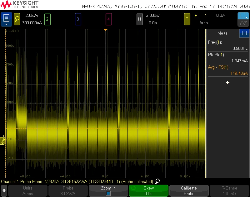
Could someone please help identify the cause of this high current draw and or the current spikes? The datasheet suggests a current consumption around 4uA at 1.8V, though I doubt the Vdd of 3.3V and the quiescent current from LDO and Buck would raise it by this much. Would be happy to share schematics privately for any advice on hardware implementation.
Thanks!
