


How to measure liquid tank level using pressure sensors
Summary
This article presents a cost-effective way to measure liquid level using pressure sensors, contrasting legacy differential sensors with modern absolute sensors and showing how ST devices like ILPS22QS and ILPS28QSW can be used for accurate water-level sensing.
1. The application
Knowing the fill level of a liquid in a tank is a critical piece of data for many applications. Measuring the fill level requires careful selection from many available sensing modalities. Radar, ultrasonic, mechanical, pneumatic bubbler, conductive, capacitive, and pressure are among the many choices. For many applications, pressure sensing hits the sweet spot for cost, precision, and reliability.
In this article, we use a washing machine tub as our target application. Water is our liquid of interest; precision should be in the mm range, with cost and high reliability heavily weighted in our guiding design constraints.
2. The physics of pressure vs. liquid height
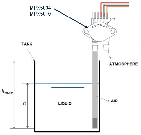
In the figure above, a differential pressure sensor is used to measure the height of water in a wash tub. The open end of a vertically oriented pressure sampling tube is positioned at the base of the tub. As the tub fills, pressure builds within the sampling tube. An air bubble or “air gap” in the sampling tube is intentional here. It prevents the direct contact of water with the MEMS pressure sensing element.
Note: Because air is compressible, the water enters upward at the base of the sensing tube to take up the space vacated by the compressed air. This means the "zero point" or the bottom of the air column shifts upward. This is a trivial error for most applications but can otherwise be characterized and calibrated out.
The pressure measured at the base of the tub is a function of the height of the water (the weight of the water) and the atmospheric pressure. In this case, the weight of our atmosphere pushing down on the surface of the water. By using a differential pressure sensor, with one port open to the atmosphere – the subtraction of the atmosphere’s contribution from the pressure measured at the base of the sampling tube is automatic. We end up with a pressure reading that is purely a function of the height of water in the tub.
P = ρ × g × h
P is pressure in pascals
ρ (rho) is the density of the liquid being measured; water is 1000 kg/m3
g is acceleration due to gravity ≈9.81 m/s2
h is the height of the liquid, in meters
Note: The diameter of the tub of water or if the sampling tube does not enter into consideration. It is only the height of the water (above the inlet of the sampling tube) that matters.
For water, and with height expressed in mm’s, that works out to:
P[in Pascals] = 9.81 × height[in mm]
Pressure increases at about 9.81 Pascals per every 1 mm of water height increase. Let us keep this number in mind when later we consider the accuracy of the measurement we are seeking versus the capability of the sensor.
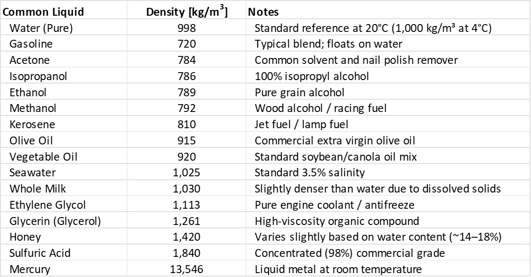
The physics holds for measuring the tank fill level of any liquid. Just be sure to plug in the correct density value for the liquid of interest. If ultimate accuracy matters in your application, then keep in mind that density varies with temperature for nearly all liquids. The volumetric thermal expansion coefficients are not conveyed in the table below. The effect is trivial for most applications.
Since atmospheric pressure is not a constant, it changes with altitude and weather conditions, we must null the effect out of the measurement. Using a differential pressure sensor can be a reasonable strategy. Referencing the image above, one port of a differential pressure sensor is exposed to the atmosphere, the other port exposed to the pressure in the vertical sensing tube. The reported pressure then is just the difference between these two pressures – just exactly what we are looking for. The pressure reading that we use for measuring the height of water is valid regardless of altitude or weather changes.
3. The legacy approach
Using a differential pressure sensor seems at first the natural selection. But these units have a few technical and a few pragmatic drawbacks to consider.
On the technical side: a large package body, through hole assembly and an analog output are among their characteristics to stay aware of. The analog output is radiometric to the power supply. Any deviation in the sensor’s power supply directly shows up in its analog output signal. The resulting strict drift and noise requirements can make for a more expensive system power supply.
The analog output is usually connected to a microcontroller’s analog-to-digital converter (ADC), so measurement accuracy depends on both the sensor supply’s noise performance and the ADC quality of the microcontroller.
On the pragmatic side: These differential pressure sensors are more expensive to produce. Because of their unique form, they have not been able to enjoy the cost and price reductions that more modern pressure sensors have.
It has become more cost effective for most applications to move on from 2-port gauge and differential type pressure sensors to more modern single-port absolute type pressure sensors.
4. The modern approach
The need for a more cost-effective gauge (or differential) pressure reading is now commonly satisfied by using absolute type pressure sensors. This is to provide both the ambient (or low side) measurement as well as the gauge (or high side) measurement. This can be done with a single sensor making an initial baseline or ambient reading, then taking the difference from subsequent readings. Alternately, the application can apply two absolute type pressure sensors (one application, the other ambient) and take the difference. Even with two modern sensors, the total system cost can be lower than when using a single differential sensor.
Most modern absolute pressure sensors on the market today have only a small orifice in the package lid. They do not include a nozzle or barbed nipple for the direct attach tubing. If the application requires the pressure signal to be conveyed by tubing, then it is up to the system designer to include a cap. The cap is typically glued to the PCB, providing a pressure chamber around the sensor. There are however a few modern sensors that do include mechanical accommodation for remote pressure conveyance. ILPS28QSW is one such device.
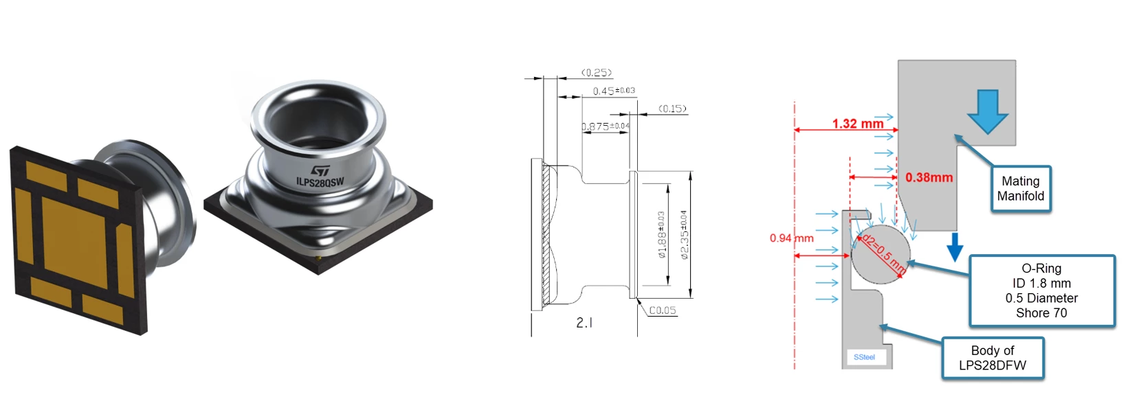
The figure above shows some of the mechanical and O-Ring details of the 2.8 x 2.8 mm 7-pin LGA package of ILPS28QSW. For more detailed applications information, refer to the following documentation:
- AN5778 – Application details covering the ILPS28QSW sensor
- AN6137 – System integration details, including O-Ring and manifold design
Let us consider the use of two modern, absolute type pressure sensors in this application. ILPS22QS is exposed to the atmosphere and provides a reference (barometric) pressure reading. ILPS28QSW is a nozzle equipped waterproof sensor and is used to measure the pressure in the tub’s sampling tube. Taking the difference of these two pressures then results in the desired differential pressure measurement.
Note: Further system BOM cost reduction is available by applying only the ILPS28QSW. In this strategy, it would be incumbent on the host MCU to use that sensor to first record the reference (Barometric) pressure reading when the tub is empty. Barometric pressure changes slowly – so any weather-induced error over the course of an hour or two can likely be safely ignored.
Note: Though waterproof, it is still a good idea to maintain the use of an air-gapped sampling tube to avoid clogging by water-borne debris. The gel covering on the sensor otherwise assures protection of the sensing element in this humid/wet environment.
|
Part |
Sensor role | Resolution [LSB/hPa] | Noise [Pa RMS] | Rel. accuracy [Pa] | Abs. Accuracy [Pa] | Notes |
| ILPS22QS | Reference | 4096 | 0.34 | 1.5 | 50 | Qvar |
| ILPS28QSW | Water height | 4096 | 0.32 | 1.5 | 50 | Waterproof |
Since these sensors handle their own analog to digital conversion, we no longer require an ADC equipped MCU. The pressure signal is transmitted digitally over an I2C bus. Transmitting the pressure signal digitally enables options regarding the sensor’s physical placement by eliminating the usual wiring restrictions associated with low amplitude analog signals.
ILPS22QS has an I2C address of 0x5C. For the ILPS28QSW, the LSB of its I2C address is established by tying its SAO pin (pin 2) either High or Low. This results in an address of either 0x5D or 0x5C; we of course choose the nonconflicting address of 0x5D. With each sensor now having a unique I2C address, both can reside on the same/shared I2C bus, saving pins on the MCU and further simplifying wiring.
A lower-cost MCU is now possible, as an ADC peripheral is no longer required.
With no error correction applied, our worst possible water height error can be figured by adding the worst-case absolute errors of these two sensor types. With each error going in the opposite direction, for a total differential error of 100 Pa. This translates to a water height error of just ≈10 mm.
With a bit of error correction applied before any water is allowed into the tub, we can zero out any absolute differences between the two sensors. The remaining error sources fall to inconsequential levels.
Related links
- Webinar on the updated pressure sensor portfolio (October 2026)
- Webinar on the industrial pressure sensors for monitoring applications in challenging environments (June 2022) (water tank discussion at minute 22.00)
- Design tip DT0153: Qvar for water-leak detection
- Application note AN5778: ILPS28QSW: dual full-scale absolute digital output barometer with Qvar detection
- Application note AN6137: ILPS28QSW digital pressure sensor: guidelines for system integration
- ILPS22QS
- ILPS28QSW