Associate II
Mar 10, 2024 4:39 AM UTC
Solved

PCB design question of Bluenrg-LPS (Bluenrg-332ac)

Hi everyone,

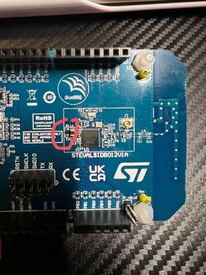
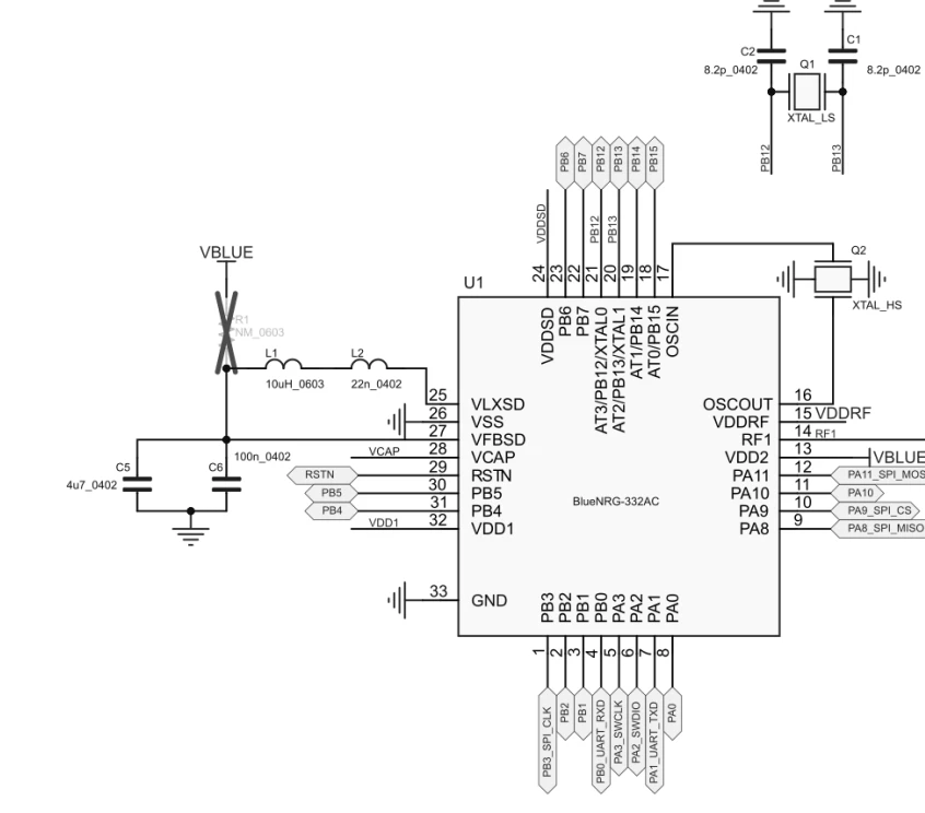
I am currently working on a PCB design using a Bluenrg-332ac chip. The official PCB design guideline has a resistor marked "X" as shown on the left of the figure below. But I saw the resistor soldered on the eval board. Can anyone explain whether we keep the resistor or not in the PCB design?

Reference files: AN5526  STEVAL-IDB012V1 
JasonYang_0-1710044982182.png

JasonYang_1-1710045176303.jpg


This topic has been closed for replies.
Laurent LOUAZON
Laurent LOUAZONBest answer
ST Employee
Mar 12, 2024 1:21 PM UTC

Hello,

This resistor should not be there.
BlueNRG gives you flexibility to use or not internal SMPS. It is a matter of power consumption versus BOM saving .

If using SMPS, then R1 must not be set
If SMPS is not used, then R1 must be set and L1/L2 are not used.

Regards
Laurent

3 replies

Laurent LOUAZON
Laurent LOUAZONBest answer
ST Employee
Mar 12, 2024 1:21 PM UTC

Hello,

This resistor should not be there.
BlueNRG gives you flexibility to use or not internal SMPS. It is a matter of power consumption versus BOM saving .

If using SMPS, then R1 must not be set
If SMPS is not used, then R1 must be set and L1/L2 are not used.

Regards
Laurent

JasonYangAuthor
Associate II
Mar 28, 2024 3:44 PM UTC

Hi Laurent,

Thank you for your reply! I also want to ask if we remove R1 here, do we still need to connect the VBLUE to the circuit?

Regards,

Jason

Laurent LOUAZON
ST Employee
Mar 28, 2024 3:54 PM UTC

Hello Jason,


If you do not set R1 , it means you will use internal SMPS (so you will have L1 and L2 set).
SMPS must be activated by SW (CONFIG_HW_SMPS_10uH)

Then Vblue is used to supply other Vdd pins of the BlueNRG-LPS (VDDSD, VDDRF, VDD1 and VDD2)


Laurent