

VL53L8CX No ACK i2C
#include "main.h"
#include <stdio.h>

/* --- Handles périphériques --- */
I2C_HandleTypeDef hi2c1;
UART_HandleTypeDef huart2;

/* --- Prototypes locaux --- */
void SystemClock_Config(void);
static void MX_USART2_UART_Init(void);
static void MX_I2C1_Init(void);
static void Sensor_Wakeup(void);
void Error_Handler(void);

/* --- Redirection printf vers UART2 --- */
#ifdef __GNUC__
int __io_putchar(int ch) {
    HAL_UART_Transmit(&huart2, (uint8_t *)&ch, 1, HAL_MAX_DELAY);
    return ch;
}
#else
int fputc(int ch, FILE *f) {
    HAL_UART_Transmit(&huart2, (uint8_t *)&ch, 1, HAL_MAX_DELAY);
    return ch;
}
#endif

int main(void)
{
    HAL_Init();
    SystemClock_Config();

    /* 1. Initialisations */
    MX_USART2_UART_Init();
    printf("\r\n========================================\r\n");
    printf("        SCANNER DE BUS I2C1 (PA9/PA10)  \r\n");
    printf("========================================\r\n");

    Sensor_Wakeup();
    MX_I2C1_Init();

    /* 2. Boucle de scan */
    while (1)
    {
        printf("\r\n--- SCAN DES ADRESSES (0x01 a 0x7F) ---\r\n");
        uint8_t count = 0;

        for (uint16_t addr = 1; addr < 128; addr++)
        {
            /* Teste chaque adresse décalée de 1 bit pour la HAL (format 8-bit) */
            if (HAL_I2C_IsDeviceReady(&hi2c1, (uint16_t)(addr << 1), 2, 5) == HAL_OK)
            {
                printf(" -> [TROUVE] Adresse 7-bit: 0x%02X | Format HAL (8-bit): 0x%02X\r\n",
                       addr, (addr << 1));
                count++;
            }
        }

        if (count == 0)
        {
            printf("Aucun composant n'a repondu sur le bus.\r\n");
        }

        HAL_Delay(2000); // Répète le scan toutes les 2 secondes
    }
}

/* --- Fonctions d'initialisation --- */

static void Sensor_Wakeup(void)
{
    __HAL_RCC_GPIOA_CLK_ENABLE();

    GPIO_InitTypeDef GPIO_InitStruct = {0};
    GPIO_InitStruct.Pin = GPIO_PIN_6;
    GPIO_InitStruct.Mode = GPIO_MODE_OUTPUT_OD;
    GPIO_InitStruct.Pull = GPIO_NOPULL;
    GPIO_InitStruct.Speed = GPIO_SPEED_FREQ_LOW;
    HAL_GPIO_Init(GPIOA, &GPIO_InitStruct);

    /* Séquence de réveil franc : reset bas puis relâchement */
    HAL_GPIO_WritePin(GPIOA, GPIO_PIN_6, GPIO_PIN_RESET);
    HAL_Delay(10);
    HAL_GPIO_WritePin(GPIOA, GPIO_PIN_6, GPIO_PIN_SET);
    HAL_Delay(100); // Marge de démarrage pour le MCU interne du ToF
}

static void MX_I2C1_Init(void)
{
    /* 1. Sélection de HSIKER pour le noyau I2C1 */
    RCC_PeriphCLKInitTypeDef PeriphClkInit = {0};
    PeriphClkInit.PeriphClockSelection = RCC_PERIPHCLK_I2C1;
    PeriphClkInit.I2c1ClockSelection = RCC_I2C1CLKSOURCE_HSIKER;
    if (HAL_RCCEx_PeriphCLKConfig(&PeriphClkInit) != HAL_OK)
    {
        Error_Handler();
    }

    /* 2. Remappage physique TSSOP-20 : PA11/PA12 -> PA9/PA10 */
    __HAL_RCC_SYSCFG_CLK_ENABLE();
    SYSCFG->CFGR1 |= (SYSCFG_CFGR1_PA11_RMP | SYSCFG_CFGR1_PA12_RMP);
    __DSB();

    /* 3. Horloges */
    __HAL_RCC_GPIOA_CLK_ENABLE();
    __HAL_RCC_I2C1_CLK_ENABLE();

    /* 4. Configuration broches 16 (PA9) et 17 (PA10) en AF6 */
    GPIO_InitTypeDef GPIO_InitStruct = {0};
    GPIO_InitStruct.Pin = GPIO_PIN_9 | GPIO_PIN_10;
    GPIO_InitStruct.Mode = GPIO_MODE_AF_OD;
    GPIO_InitStruct.Pull = GPIO_NOPULL;
    GPIO_InitStruct.Speed = GPIO_SPEED_FREQ_HIGH;
    GPIO_InitStruct.Alternate = GPIO_AF6_I2C1;
    HAL_GPIO_Init(GPIOA, &GPIO_InitStruct);

    /* 5. Reset matériel du contrôleur I2C */
    __HAL_RCC_I2C1_FORCE_RESET();
    HAL_Delay(5);
    __HAL_RCC_I2C1_RELEASE_RESET();
    HAL_Delay(5);

    /* 6. Paramètres I2C1 (100 kHz standard mode pour HSI) */
    hi2c1.Instance = I2C1;
    hi2c1.Init.Timing = 0x00303D5B;
    hi2c1.Init.OwnAddress1 = 0;
    hi2c1.Init.AddressingMode = I2C_ADDRESSINGMODE_7BIT;
    hi2c1.Init.DualAddressMode = I2C_DUALADDRESS_DISABLE;
    hi2c1.Init.GeneralCallMode = I2C_GENERALCALL_DISABLE;
    hi2c1.Init.NoStretchMode = I2C_NOSTRETCH_DISABLE;

    if (HAL_I2C_Init(&hi2c1) != HAL_OK)
    {
        Error_Handler();
    }
}

static void MX_USART2_UART_Init(void)
{
    __HAL_RCC_GPIOA_CLK_ENABLE();
    __HAL_RCC_USART2_CLK_ENABLE();

    GPIO_InitTypeDef GPIO_InitStruct = {0};
    GPIO_InitStruct.Pin = GPIO_PIN_2 | GPIO_PIN_3;
    GPIO_InitStruct.Mode = GPIO_MODE_AF_PP;
    GPIO_InitStruct.Pull = GPIO_NOPULL;
    GPIO_InitStruct.Speed = GPIO_SPEED_FREQ_LOW;
    GPIO_InitStruct.Alternate = GPIO_AF1_USART2;
    HAL_GPIO_Init(GPIOA, &GPIO_InitStruct);

    huart2.Instance = USART2;
    huart2.Init.BaudRate = 115200;
    huart2.Init.WordLength = UART_WORDLENGTH_8B;
    huart2.Init.StopBits = UART_STOPBITS_1;
    huart2.Init.Parity = UART_PARITY_NONE;
    huart2.Init.Mode = UART_MODE_TX_RX;
    huart2.Init.HwFlowCtl = UART_HWCONTROL_NONE;
    huart2.Init.OverSampling = UART_OVERSAMPLING_16;
    huart2.Init.OneBitSampling = UART_ONE_BIT_SAMPLE_DISABLE;

    if (HAL_UART_Init(&huart2) != HAL_OK)
    {
        Error_Handler();
    }
}

void SystemClock_Config(void)
{
    RCC_OscInitTypeDef RCC_OscInitStruct = {0};
    RCC_ClkInitTypeDef RCC_ClkInitStruct = {0};

    RCC_OscInitStruct.OscillatorType = RCC_OSCILLATORTYPE_HSI;
    RCC_OscInitStruct.HSIState = RCC_HSI_ON;
    RCC_OscInitStruct.HSICalibrationValue = RCC_HSICALIBRATION_DEFAULT;
    if (HAL_RCC_OscConfig(&RCC_OscInitStruct) != HAL_OK)
    {
        Error_Handler();
    }

    RCC_ClkInitStruct.ClockType = RCC_CLOCKTYPE_HCLK | RCC_CLOCKTYPE_SYSCLK | RCC_CLOCKTYPE_PCLK1;
    RCC_ClkInitStruct.SYSCLKSource = RCC_SYSCLKSOURCE_HSI;
    RCC_ClkInitStruct.SYSCLKDivider = RCC_SYSCLK_DIV1;
    RCC_ClkInitStruct.AHBCLKDivider = RCC_HCLK_DIV1;
    RCC_ClkInitStruct.APB1CLKDivider = RCC_HCLK_DIV1;

    if (HAL_RCC_ClockConfig(&RCC_ClkInitStruct, FLASH_LATENCY_1) != HAL_OK)
    {
        Error_Handler();
    }
}

void Error_Handler(void)
{
    __disable_irq();
    while (1)
    {
    }
}
Hello,
I have a problem with my VL53L8CX sensor ToF
I use STM32CO71 on a PCB, with 2 levels of tension 1,8V and 3,3V.
For convert levels of tension i use TXS0108E 8-Bit Bi-Directional, Level-Shifting, Voltage Translator for Open-Drain and Push-Pull Applications.
This permit to have 1V8 for the tof (AVDD supply in 3V3) and 3V3 for STM32.
I have succes to have the I2C signal on sda lines for the 1V8 and 3V3 part on oscilloscope :
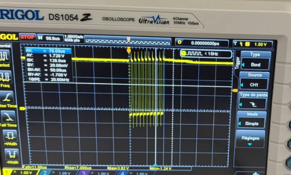
But when i’m connecting in i2C, i make a scan i2C (you can see the code C). The problem is that i have a NACK (not acknowledged) when i scan i2C bus. I changed my ToF many time so i can’t say that is a hardware problem.
You can see my shematic :
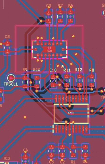
What can i do for succes to have a response by the ToF ?
Thank you so much