

Associate
August 3, 2026
Question

VL53L4CX calibration value instability

  • August 3, 2026
  • 6 replies
  • 105 views

Hello, we have obtained some VL53L4CX sensors and are having a hard time calibrating them. We have created a 3D printed test jig which positions the sensor exactly 100mm away from a 17% greycard as instructed by the datasheet. We’re running the ULD driver. It all appears to work correctly, but now we would like to calibrate the offset and xtalk. The methods run correctly but the returned values appear to shift over time and between runs. We modified the ULD driver to inject debugging statements to see the measured values. Attached are 4 different runs showing how the values have some trend/wave pattern to them, which biases the averaging and results in a wrong computed offset, and one that changes over time. This calibration is done inside a box which is in near absolute darkness so it’s not ambient light that’s affecting it.
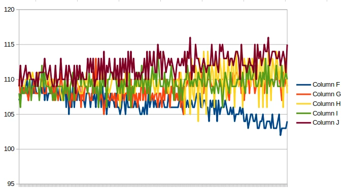
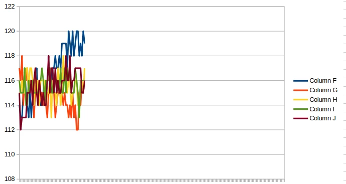


Advise would be highly appreciated, as this is a major blocker to our product thus far.


Best regards

6 replies

ST Technical Moderator
August 21, 2026

Hi,

According to   UM2923 (A guide to using the VL53L4CX Time-of-Flight sensor with extended distance measurement - User manual), a complete VL53L4CX customer factory calibration   should be performed in   three steps, and the order is important:

1.   RefSPAD calibration   
2.   Xtalk calibration   
3.   Offset calibration  

So, the sequence is:

  RefSPAD → Xtalk → Offset  

 1. complete calibration flow

After power-up, the standard initialization should be:

VL53LX_WaitDeviceBooted();
VL53LX_DataInit();
   
Then run the three calibrations in the following order:

VL53LX_PerformRefSpadManagement();
VL53LX_PerformXTalkCalibration();

VL53LX_PerformOffsetSimpleCalibration(...); or VL53LX_PerformOffsetPerVCSELCalibration(...);
   

After calibration, the results should be retrieved and stored on the host side:

VL53LX_GetCalibrationData();

At every next startup, instead of recalibrating, the saved calibration data should be reloaded after  DataInit()  using:

VL53LX_SetCalibrationData();
   

Please also note that the calibration flow changes the distance mode internally, so if the sensor is used immediately after calibration, it is mandatory to call: VL53LX_SetDistanceMode() again, before normal ranging.

2. RefSPAD calibration

RefSPAD calibration optimizes the number and location of SPADs used by the device. 
ST recommends performing it in the final product configuration, especially if a cover glass is present.

Setup
No special target is needed. 
The only requirement is: No target in front of the sensor  

Function

VL53LX_PerformRefSpadManagement(&Dev);

This step must be executed first.

3. Xtalk calibration

Xtalk calibration compensates for the parasitic signal caused by internal reflections in the cover glass.

Required setup
According to   UM2923  , Xtalk calibration should be performed with:

-   17% grey target  
-   600 mm distance  
-   Dark environment  
-   No IR contribution  

Function

VL53LX_PerformXTalkCalibration(&Dev);

This step must be executed   after RefSPAD calibration   and   before offset calibration .

Important note
Xtalk compensation is   disabled by default  , so after calibration or after loading saved calibration data, it should be explicitly enabled:

VL53LX_SetXTalkCompensationEnable(&Dev, 1);

4. Offset calibration

Offset calibration compensates for the distance shift introduced by PCB soldering, mechanical assembly, and/or cover glass integration.

Required setup
For offset calibration, the setup is more flexible:

-   Any chart reflectance  
-   Any known distance  
-   Dark environment / no IR contribution  

However, one important condition must be respected: 2MCps<Signal Rate<80MCps
So the target distance and reflectance can be chosen freely, as long as the measured signal rate stays within this range.

Function:
Standard offset calibration:

VL53LX_PerformOffsetSimpleCalibration(&Dev, CalDistanceMilliMeter);

More accurate per-VCSEL offset calibration:

VL53LX_PerformOffsetPerVCSELCalibration(&Dev, CalDistanceMilliMeter);
   
Recommendation
The   PerVCSEL   method is recommended by default because it provides better accuracy, although it takes longer.

If this method is used, the correction mode must also be set explicitly:

VL53LX_SetOffsetCorrectionMode(&Dev, VL53LX_OFFSETCORRECTIONMODE_PERVCSEL);
   
If the simple offset calibration is used instead, then the mode should be:

VL53LX_SetOffsetCorrectionMode(&Dev, VL53LX_OFFSETCORRECTIONMODE_STANDARD);
   

5. Saving and reloading calibration data

After all three calibration steps are completed, the full calibration structure should be read back and stored in host non-volatile memory:

VL53LX_GetCalibrationData(&Dev, &cal_data);
   
At each next power-up, the recommended startup flow is:
VL53LX_WaitDeviceBooted();
VL53LX_DataInit();
VL53LX_SetCalibrationData(&Dev, &cal_data);
VL53LX_SetXTalkCompensationEnable(&Dev, 1);
VL53LX_SetOffsetCorrectionMode(&Dev, VL53LX_OFFSETCORRECTIONMODE_PERVCSEL); // if per VSCEL offset was used
VL53LX_SetDistanceMode(&Dev, ...);
   
This avoids repeating the factory calibration every time.

6. Important practical notes

A few common points to pay attention to:

- The calibration order must remain   RefSPAD → Xtalk → Offset  
- If calibrations are done individually, the previous calibration data must be loaded first
- Xtalk compensation is   not automatically enabled  
- Offset correction mode is   not automatically selected  
- After calibration,  distance mode must be set again  
- For offset calibration, the key condition is not the absolute distance itself, but keeping the signal rate within the valid range

Best Regards,

Bin FAN

In order to give better visibility on the answered topics, please click on 'Accept as Solution' on the reply which solved your issue or answered your question.
zek_krisAuthor
Associate
August 21, 2026

Hello,


Thank you for your response. When you say no target in front of the sensor what does that actually entail? A specific distance in front of the sensor or over the sensor’s maximum range (for this one 6m). Would then pointing it up at the sky suffice or does it need to be in dark conditions?


Our current test setup consists of a dark box in which the sensor is positioned exactly 100mm away from a 17% greycard.


Best regards.


zek_krisAuthor
Associate
August 21, 2026

After doing this calibratio (with refspad pointing at nothing), results improved somewhat however we still see this waveform repeat every time we start the sensor up. 


ST Technical Moderator
August 25, 2026

Hello,

Thank you for your feedback.

Regarding the behavior you observed, please find below a few clarifications:

  1. RefSPAD calibration and Xtalk calibration are typically part of the same complete factory calibration flow.
    Since different customers may use different mechanical assemblies and different cover glass configurations, calibration is recommended in the final product setup.
    In this flow, RefSPAD calibration must be performed first, and one of its purposes is to prepare the device configuration for the subsequent Xtalk calibration step.

  2. RefSPAD calibration requires no target in front of the sensor.
    In practice, this means that during the RefSPAD calibration step, there should be no intended close target in front of the sensor, and no significant target return should be present in the effective field of view. the setting of Xtalk calibration (17% grey target,600 mm distance, Dark environment, No IR contribution) is ok for RefSPAD calibration, just make sure there are no targets within a range of 100mm.

  3. It is recommended to treat calibration and normal ranging as two separate phases.
    A typical flow is the following:

Step 1: Perform RefSPAD calibration and Xtalk calibration, then read back and store the calibration data

Step 2: Perform Offset calibration, then store the corresponding offset data

At this point, the calibration phase is complete

Step3: At the next power-up, the recommended approach is to reload the saved calibration data instead of repeating the full calibration flow.

The recommended startup sequence is:

VL53LX_WaitDeviceBooted();

VL53LX_DataInit();
VL53LX_SetCalibrationData(&Dev, &cal_data);
VL53LX_SetXTalkCompensationEnable(&Dev, 1);
VL53LX_SetOffsetCorrectionMode(&Dev, VL53LX_OFFSETCORRECTIONMODE_PERVCSEL); // if per-VCSEL offset was used
VL53LX_SetDistanceMode(&Dev, ...);


Hope this can help you. Thanks~

Best Regards,

Bin FAN

In order to give better visibility on the answered topics, please click on 'Accept as Solution' on the reply which solved your issue or answered your question.
Graduate
August 27, 2026

Everything Bin said is exactly correct, but there maybe a few practical thoughts. 

  1. if you don’t have a coverglass - crosstalk cannot exist. So, you can skip that.
  2. RefSpad - that 100mm is right on the cusp of being too close.
  3. Building a larger calibration box at say 15cm might be best - unless close targets are what you are worried about. 
  4. but what I generally suggest is building a 60cm box, with a flap you can fold down. Do the refSPAD and the Xtalk. Then fold down that flap and do the offset and the testing. Fold it back up for the next chip.

But have a look at the section on accuracy. ST would dearly love to guarantee mm accuracy, but photons are too fast for an inexpensive sensor - so statistics are involved.  +/- 3% is the best that can be guaranteed, and even that breaks down in the very close distances. Your waveform - is within the 3% range.

It appears to me that after the VCSELs (laser) heats the chip to steady state, you get tighter numbers. The sensor does account for temperature, but it only adjusts for temp every couple of degrees C.

I’m retired - but still interested.

Good luck

"If this or any post solves your issue, please mark them as ""Accept as Solution"". It really helps the next guy.And if you notice anything wrong do not hesitate to ""Report Inappropriate Content"".I am a recently retired ST Employee. My former username was John E KVAM."
zek_krisAuthor
Associate
August 28, 2026

Hello, Thank you for your answer!

Since my previous response, we’ve built a 600mm box and are doing refspad and xtalk at that distance, then doing offset at 100mm. 

We’ve tried 2 types of cover glass: the Gilisymo ones recommended by ST as well as ones that alter the optical path for focusing at a long distance. The recommended cover glass does not alter the behavior which is expected. The focusing glass does, yielding vastly improved performance at longer distances as much less high frequency noise, however it results in very erratic behavior at close distances. The behavior almost looks like it fits a standard 2nd order system, which might be indicative of the sensor controlling the number of SPADs to attempt to “autofocus”.


Our sensor application is battery powered and we can only ever afford at most a dozen measurements every time we wake up from sleep. We control the chip power completely, not just xshut, which as explained in other topics should also do temperature compensation.

As indicated by the graphs unfortunately the first dozen measurements can either be erratic or under-range.

We’re specifically chasing the issue in the closer ranges under 100mm as over 100mm we’re satisfied with the performance.


Its important to state that these expectations are in-line with some competitor products we’ve analyzed which use ST’s ToF sensors as well. We’ve observed +-2mm precision sub 100mm on one product using the VL53L0X and we’re unable to match that performance ourselves on the L4. Perhaps there are more insights to be gained on this sensor