Associate
June 10, 2026
Solved

Issue with I2C communication with VL53L4CD

  • June 10, 2026
  • 3 replies
  • 34 views

Hello everyone.


I am trying to communicate with a VL53L4CD on my PCB, on the same I2C Bus I have a LP LED Matrix Controller and an EEPROM that work just as I hoped they would. 


But none of the VL53L4CD seem to be able to communicate over the Bus. I have by now tried to look at everything possibly wrong with it. 


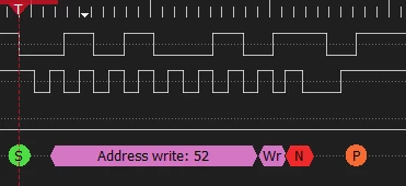
Software: The Software gives out the exact I2C Signal I would be expecting (Address 0x52 (derived from 0x29 of course)) but I always get NACK’s, 


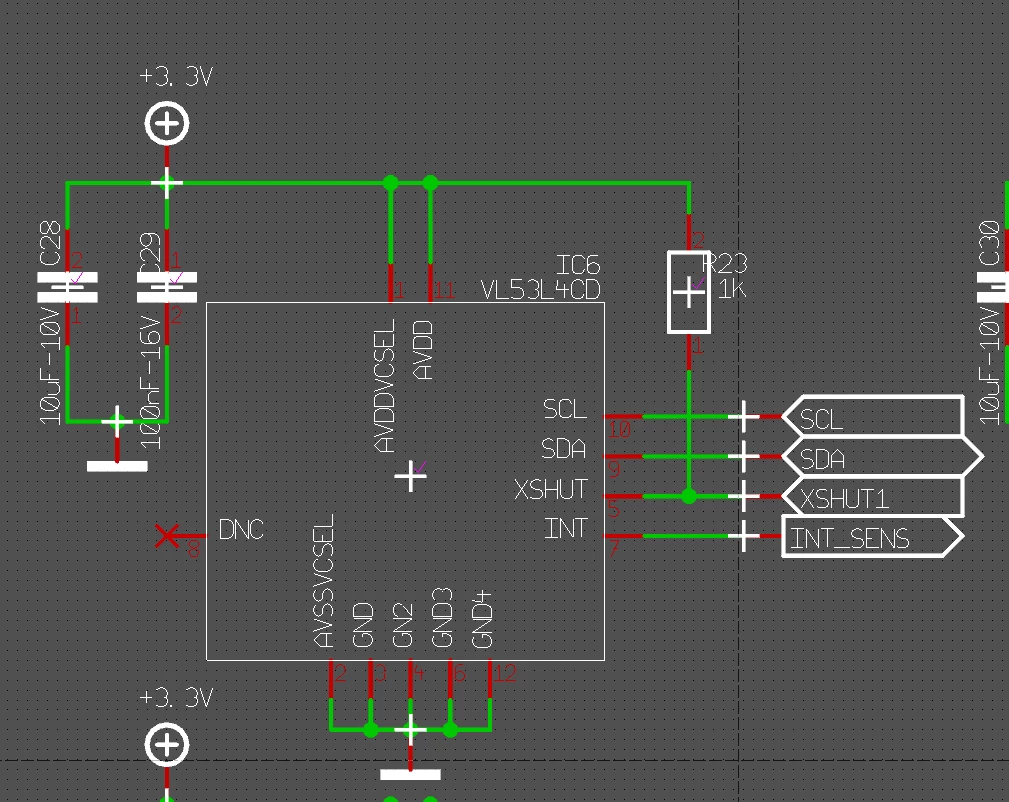
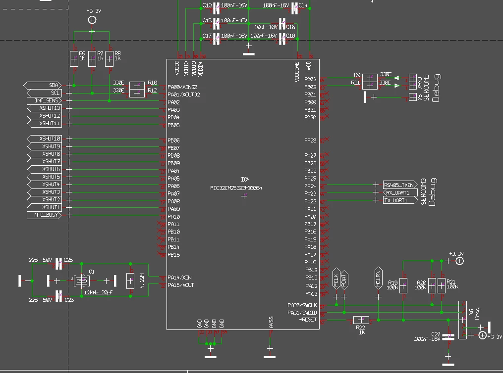
Hardware: All Sensors are on the same bus, where I Chip Select via the XSHUT Pins, those forms also look correct and only the one is high where I want to talk to the sensor, so there’s not 2 sensors that could respond to the same address having XSHUT on the same niveau. 

I have tested the connection to the pads, and those are all correct, so is the Power SUpply and GND to the Chip all of those seem correct according to the Datasheet. 


My I2C Bus runs on 100kHz which as far as I can tell should work with the Sensor. 


Furthermore I have hooked up a little testboard we had lying around with the same sensor where I hoped maybe all of the mounted ones are fried but not even that one is reacting with an ACK.


Also I’ve tested a complete Scan of what’s on the I2C Bus and all that gave me was the LP and the EEPROM Addresses that responded. I am by now completely vexxed with what else I can try to get this working.

Bus Scan
Sensor Schematic
Microcontroller Schematic


Best answer by Sennji

[SOLVED]


If anyone sees this in the future, my Issue was the Voltage divider I’ve put on the I2C Bus, which meant when sending a logical 0 it was barely below 1V which the sensor didn’t register as logical 0.


Solution was to replace the 330 Ohms serial resistor with a 0 Ohm one. 

3 replies

Yassine_behilil
Graduate II
June 10, 2026

Hi,

I had a very similar symptom with a VL53L4Cx device: the I2C bus itself was fine, other slaves answered correctly, but the ToF sensor always NACKed.

In my case the root cause was not the I2C controller or the address. It was the IO/power/reset side of the ToF sensor.

Things I would check in this order:

1. Use the correct address format
   - Linux / normal 7-bit I2C scan: 0x29
   - ST documentation/API often writes it as 0x52, which is the 8-bit write address.
   - So seeing 0x52 in the waveform is OK if your software API expects 8-bit addresses, but an i2cdetect-style scan should show 0x29.

2. Check XSHUT with a scope
   - If XSHUT is low, the VL53L4CD will not answer at all.
   - Make sure only one sensor is released if several sensors share the default address.
   - After driving XSHUT high, wait long enough before the first I2C access.

3. Check both sensor supply and IO supply/domain
   - Verify the sensor power rails directly at the package pins.
   - Also verify the I2C pull-up voltage matches the sensor IO voltage.
   - On my platform, the missing part was the VDDIO / IO domain for the I2C pins. Other I2C devices worked, but the VL53 still never ACKed until the IO domain was enabled correctly.

4. If using Linux or an ST kernel driver, verify reset GPIO handling
   - Some ST drivers use legacy DT properties such as `xsdn-gpio` / `intr-gpio`.
   - More recent Linux-style bindings use `reset-gpios` / `interrupts`.
   - If the driver does not parse the reset GPIO it expects, XSHUT may never be released, and the device will look dead on I2C.

5. Scope the ACK bit
   - Confirm SDA/SCL levels and rise times.
   - Confirm XSHUT is high before the address phase.
   - Confirm the device still NACKs at 0x29 after power and reset are valid.

So I would not focus first on 100 kHz I2C; that should be fine. If the scan does not show 0x29, the most likely causes are XSHUT, power/IO voltage domain, pull-ups, or the wrong GPIO/reset handling.

SennjiAuthor
Associate
June 10, 2026

Hey Yassine, thanks for the quick reply.


  1. Yes for the scan I do expect to see 0x29 if it can communicate. For redundancys sake I’ve tested with both addresses (just so I am not missing something) 
  2. XSHUT is at 3.3V’s when I expect it to be, all other XSHUT’s are on 0 so that doesn’t seem to be the issue here. I do wait for 10ms after turning XSHUT high (which should be 8 times as long as needed) 
  3. I can’t get to the PAckage pins as they’re below the only thing I can certainly tell is that the VDD and AVDDCSEL does receive 3.3V on the board pins (soldered a sensor of for this) what I can’t say 100% is that all sensors are cleanly soldered in the first place. but we have such a reflow machine that I deem it highly unlikely that all 13 would be crashing out. (And also the extra one I’ve added after) but from what I can tell all power is there that’s needed. 
    The Pull-Up Voltage I’ve confirmed. that also sits at the 3.3V rail.
  4. In regards to driver, I am on barebone MPLAB Harmony, and am setting the GPIO definitions there.
    I could imagine that I’ve made an error there, but due to the fact that I2C communciation with the other slaves work, I presume it’d be somewhere else where the error is.
  5. I have confirmed both SDA and SCL get to the 3.3V level and the rise times seem clean.
    I have confirmed XSHUT is high before I try addressing it
    As far as I can tell, yes all seems valid but still getting only NACK’s at 0x29
SennjiAuthorBest answer
Associate
June 12, 2026

[SOLVED]


If anyone sees this in the future, my Issue was the Voltage divider I’ve put on the I2C Bus, which meant when sending a logical 0 it was barely below 1V which the sensor didn’t register as logical 0.


Solution was to replace the 330 Ohms serial resistor with a 0 Ohm one.