


After replacing TI's LM258DR with ST's LM258DT, it will not work
Dear ST support team
As shown in the diagram, I use a current transformer (PT1) and an amplifier to measure AC voltage:
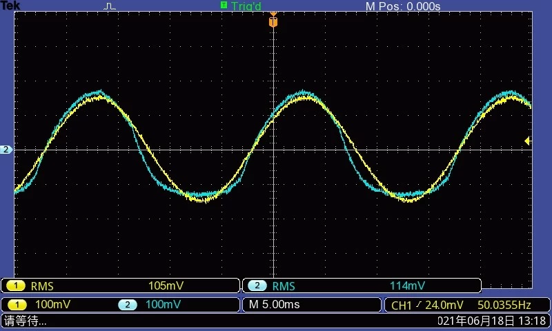
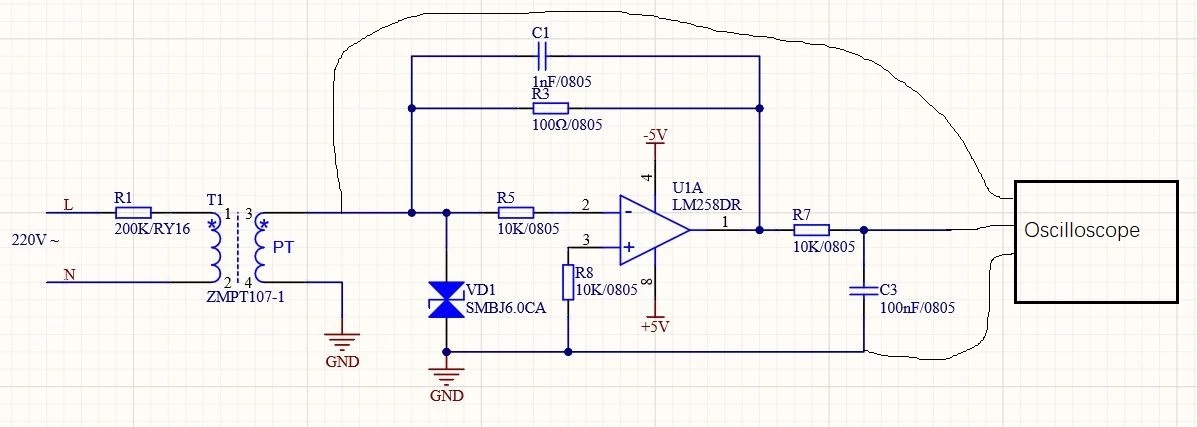 When U1A is LM258DR of TI, the system works perfectly well. After replacing U1A with LM258DT of ST, the waveform measured by the oscilloscope is distorted. The following picture is a screenshot of the oscilloscope, the yellow is the waveform of the circuit using LM258DR, and the blue is the ST chip:
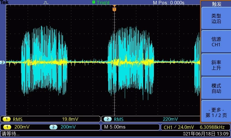
 The model of T1 is ZMPT107-1, which is a transformer of 2mA/2mA. When I tested the 3-foot waveform of T1, I found abnormal condition: Because of the feature of OP AMP, the current output from T1 goes through R3, and there is no current coming in from 2-foot of OP AMP, so the voltage of T1 3-foot should be equal to 0. In circuit using TI chip, this is true, but in circuit using ST chip,There is a strange waveform. The yellow one in the TI chip circuit and the blue one in the ST chip circuit are shown below:
 According to the datasheet, the parameters of LM258DR and LM258DT are very similar. Why is this problem? How can I solve this problem?
Thank and Best Regard.