Turn on suggestions
Auto-suggest helps you quickly narrow down your search results by suggesting possible matches as you type.
Showing results for
- STMicroelectronics Community
- MEMS and sensors
- MEMS (sensors)
- I am using your AIS2DW12 Three axis accelerometer....
Options
- Subscribe to RSS Feed
- Mark Topic as New
- Mark Topic as Read
- Float this Topic for Current User
- Bookmark
- Subscribe
- Mute
- Printer Friendly Page
I am using your AIS2DW12 Three axis accelerometer. Unfortunately I have faced a problem which I am not able to solve.
After my define timer deactivated my expectation is INT1 Voltage drop down . This happens but with some curve which i don't know why?
Options
- Mark as New
- Bookmark
- Subscribe
- Mute
- Subscribe to RSS Feed
- Permalink
- Email to a Friend
- Report Inappropriate Content
2020-07-20 01:07 AM
6 REPLIES 6
Options
- Mark as New
- Bookmark
- Subscribe
- Mute
- Subscribe to RSS Feed
- Permalink
- Email to a Friend
- Report Inappropriate Content
2020-07-20 02:52 AM
Hi @Yeko.ER, to better understand if it can be a circuit or device related issue, are you seeing a curve falling-edge front of the interrupt pulse? Can you please check on the schematic of your application (or share it) if there are any parasitic resistance or capacitance? Or if the acquisition path along the INT line is buffered, even if the INT1 pin is by default a push-pull output forced to Gnd (datasheet p.24). Btw, how did you configured the interrupt parameters (pulsed/latched, duration in case of specific motion detection, etc...) Regards
Options
- Mark as New
- Bookmark
- Subscribe
- Mute
- Subscribe to RSS Feed
- Permalink
- Email to a Friend
- Report Inappropriate Content
2020-07-20 07:45 AM
Hi @Eleon BORLINI ,
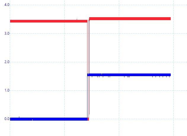
for better understanding I can share two pictures from Scope. If the Motion sensor power supply is 1.8 V there is no ramp and INT1 works clean. If i set power supply to 3.0 V then i see the ramp. Here is also my configuration for Activity in motion sensor same as ST application notes. If i just have a correct definition for this differences and reason of it, could be helpful to me. The red line is INT1 and blue one is Power supply. With regards
void Motion_Active(void) {
uint16_t reg_val_U8 = 0;
reg_val_U8 = Motion_ReadRegister(AIS2DW12_WHO_AM_I); // read Product revision info 1.0 = 0x10
// enable soft reset
Motion_WriteRegister( AIS2DW12_CTRL2 , 0x44);
_NOP;
// enable Lacactive
Motion_WriteRegister( AIS2DW12_CTRL6 , 0x40);
_NOP;
// Turn on the accelerom and set ODR Power mode 100
Motion_WriteRegister( AIS2DW12_CTRL1 , 0x53);
_NOP;
// Set duration of inactvity and wakeup
Motion_WriteRegister( AIS2DW12_WAKE_UP_DUR , 0x42);
_NOP;
// Set threshold of inactvity and wakeup
Motion_WriteRegister( AIS2DW12_WAKE_UP_THS , 0x42);
_NOP;
// Actvitiy wakeup interrupt to INT1 pin
Motion_WriteRegister( AIS2DW12_CTRL4_INT1 , 0x20);
_NOP;
// enable Lacactive
Motion_WriteRegister( AIS2DW12_CTRL3 , 0x08);
_NOP;
// enable Lacactive
Motion_WriteRegister( AIS2DW12_CTRL7 , 0x20);
_NOP;
}
Options
- Mark as New
- Bookmark
- Subscribe
- Mute
- Subscribe to RSS Feed
- Permalink
- Email to a Friend
- Report Inappropriate Content
2020-07-20 07:45 AM
Options
- Mark as New
- Bookmark
- Subscribe
- Mute
- Subscribe to RSS Feed
- Permalink
- Email to a Friend
- Report Inappropriate Content
2020-07-20 07:47 AM
Options
- Mark as New
- Bookmark
- Subscribe
- Mute
- Subscribe to RSS Feed
- Permalink
- Email to a Friend
- Report Inappropriate Content
2020-07-22 07:37 AM
Hi @Yeko.ER , please help me to understand... in the picture here above, the Blue line is 1.8V (are they Volts on Y axis and maybe milliseconds on X axis? Why the Red line is going down and then up when the blue line remains down? Regards
Options
- Mark as New
- Bookmark
- Subscribe
- Mute
- Subscribe to RSS Feed
- Permalink
- Email to a Friend
- Report Inappropriate Content
2020-07-22 01:48 PM
Thanks for your comment. Yes , you have got it correct. X axis is Voltage and Y is millisecond. Red line is INT1 and Blue Line is Voltage for Hardware which i have connected to AIS2DW12 . My expectation and aim was after wake-up duration INT1 deactivate my Hardware and it is correct. " Why the Red line is going down and then up when the blue line remains down?" This is exactly my Problem and reason i have asked here. Asyou can see in the last picture it is correct but there the Hardware voltage has already set to 1.8 and here with this funny curve hardware Voltage is 3.6.
Well simply we can say it is like this. Set AIS2DW12 Supply Voltage on 1.8. But i should know the reason why i have this Curve when i set supply Voltage to 3.6. In datasheet there is nothing about Typ or Max voltage.
BR,
Related Content
- LSM6DS3H ACCELEROMETER Bias reproducibility in MEMS (sensors)
- LSM6DSL gyroscope high-pass filter reset in MEMS (sensors)
- Spikes in the LIS2DH12 accelerometer raw data in MEMS (sensors)
- LIS2DW12 latching INT1 pin to GND on board reboot in MEMS (sensors)
- Dead-reckoning over small distances with IMU sensor LSM6DSV16B in MEMS (sensors)