Turn on suggestions
Auto-suggest helps you quickly narrow down your search results by suggesting possible matches as you type.
Showing results for
- STMicroelectronics Community
- STM32 MCUs Software development tools
- STM32CubeIDE (MCUs)
- STM32 minimalistic project template WITHOUT STM32C...
Options
- Subscribe to RSS Feed
- Mark Topic as New
- Mark Topic as Read
- Float this Topic for Current User
- Bookmark
- Subscribe
- Mute
- Printer Friendly Page
STM32 minimalistic project template WITHOUT STM32CubeIDE C Code generation. How to include ST HAL and/or LL drivers into an empty project?
Options
- Mark as New
- Bookmark
- Subscribe
- Mute
- Subscribe to RSS Feed
- Permalink
- Email to a Friend
- Report Inappropriate Content
2020-04-23 12:00 AM
Hi there
I moved from TI DSPs using Code Composer Studio to a STM32F4 MCU using STM32CubeIDE and I already struggle with the first steps. While I fancy the automatic Code generation that the STM32CubeIDE configurator offers, I would like to start my first projects without it in order to get a better understanding of the MCU and the CubeIDE.
I am coming straight to the point:
- How do I best create an empty project such that I afterwards include the pre-defined functions (peripherals such as ADC, Timers etc.)?
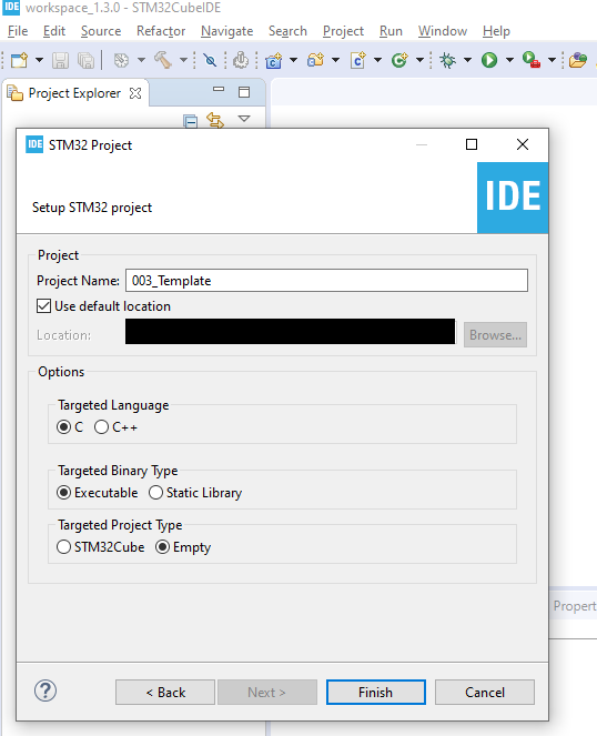
- My current approach has been: File->New->STM32 Project->Target Project Type: Empty (shown in figure CubeIDE)
- This seems to do the job (shown in CubeIDE1). But that brings me directly to question nr 2:
- Once I have this empty project, I would like to include the necessary pre-defined functions, header files etc. Where and how in the CubeIDE (project settings) do I do the proper linking and including (see CubeIDE2)?
- I have downloaded the STM32CubeF4 driver package and read the getting started manual. So now the question is how to include the necessary driver files into my project via STMCubeIDE.
- Is there any document that describes this procedure and the required header files/driver files etc?
I hope I am not asking for too much help here.
Thank you,
Labels:
- Labels:
-
STM32CubeIDE
-
STM32F4 Series
13 REPLIES 13
Options
- Mark as New
- Bookmark
- Subscribe
- Mute
- Subscribe to RSS Feed
- Permalink
- Email to a Friend
- Report Inappropriate Content
2020-04-23 07:36 AM
For the LL/HAL files its easy:
in the STM32CubeF4 driver package locate the folder "\STM32Cube_FW_F4_V1.25.0\Drivers" an copy it in your project folder: il will appear in the IDE (or copy only inc and src folders).
Remenber to set the path to this inc folder in your project properties.
You will also need the CMSIS file for your STM32 device, in : STM32Cube_FW_F4_V1.25.0\Drivers\CMSIS\Device\ST\STM32F4xx\Include
and also : \STM32Cube_FW_F4_V1.25.0\Drivers\CMSIS\Include
Etc. Search into this Drivers folder, you will find everything you need.
Options
- Mark as New
- Bookmark
- Subscribe
- Mute
- Subscribe to RSS Feed
- Permalink
- Email to a Friend
- Report Inappropriate Content
2020-04-23 11:49 AM
I would not recommend starting from an empty project if you intend using HAL and/or LL drivers and STM32CubeIDE anyway. There are many tool settings like include paths, prepocessor defines etc.. which you have to copy. And, there is the linker description (.ld) file and probably the startup file that you want to reuse.
A minimalistic generated project does not contain much more than that plus some init functions in main().
You can delete everything you dont want and never re-generate the code again. Add missing HAL/CMSIS drivers as described by @Nikita91 above.
Some people don't like HAL very much. You can make up your mind by learning from small examples. You can even use register level programming in the generated project or mix that with HAL. All CMSIS register defines are readily available for you.
I have compiled some "blinky" examples using different approaches here https://gitlab.com/stm32mcu/wiki/-/wikis/home#blinky-the-embedded-hello-world
Options
- Mark as New
- Bookmark
- Subscribe
- Mute
- Subscribe to RSS Feed
- Permalink
- Email to a Friend
- Report Inappropriate Content
2020-04-23 12:00 PM
Hi KnarfB
you're probably right. But I still don't like the approach for me to use the graphic interface that afterwards generates the necessary code for me. I would like to use the functions and header files from HAL (or LL) setup the MCU myself.
Then let me ask you:
Is there any approach in between starting an empty project from scratch (my initial approach) together with using the STM32CubeIDE configuration + automatic code generation?
Thank you,
Options
- Mark as New
- Bookmark
- Subscribe
- Mute
- Subscribe to RSS Feed
- Permalink
- Email to a Friend
- Report Inappropriate Content
2020-04-23 12:02 PM
Just to be sure that I am not misunderstood with my previous sentence about the "approach in between" : This would be what you are referring to "A minimalistic generated project does not contain much more than that plus some init functions in main()."
Options
- Mark as New
- Bookmark
- Subscribe
- Mute
- Subscribe to RSS Feed
- Permalink
- Email to a Friend
- Report Inappropriate Content
2020-04-23 01:17 PM
Exactly. You dont have to configure your timers, SPI,... graphically. You can do it later by programming at your level of choice (HAL, LL, CMSIS register level).
Try New > STM32 Project, pick a chip of your choice, step through the wizard with all defaults and the generated main() looks like
int main(void)
{
  HAL_Init();
  SystemClock_Config();
  while (1)
  {
  }
}
(all comment omitted). Build you project and test (debug) it. Then, you may throw away the .ioc file and you have a known good starting point.
Btw: I like to keep the .ioc file at least for chip planning and configuring the IO pads graphically, but this is a matter of taste.
Options
- Mark as New
- Bookmark
- Subscribe
- Mute
- Subscribe to RSS Feed
- Permalink
- Email to a Friend
- Report Inappropriate Content
2020-04-23 10:40 PM
Hi KnarfB - I truly appreciate your help here. I did create a STM32 project and chose my MCU and I went through the wizard. My generated main.c looks so heavy for my taste. Honestly, I do not understand why my GPIO, I2C, SPI and USB are already initialized and have their initialization functions generated in the main.c file. Also, I do not understand why there is only a fraction of my HAL functions in the project, and only one LL function? For instance, I cannot see the HAL for ADC/DAC (see the attached picture)?
/* Includes ------------------------------------------------------------------*/
#include "main.h"
#include "usb_host.h"

/* Private variables ---------------------------------------------------------*/
I2C_HandleTypeDef hi2c1;

I2S_HandleTypeDef hi2s3;

SPI_HandleTypeDef hspi1;

/* Private function prototypes -----------------------------------------------*/
void SystemClock_Config(void);
static void MX_GPIO_Init(void);
static void MX_I2C1_Init(void);
static void MX_I2S3_Init(void);
static void MX_SPI1_Init(void);
void MX_USB_HOST_Process(void);


int main(void)
{
  /* Reset of all peripherals, Initializes the Flash interface and the Systick. */
  HAL_Init();

    /* Configure the system clock */
  SystemClock_Config();

   /* Initialize all configured peripherals */
  MX_GPIO_Init();
  MX_I2C1_Init();
  MX_I2S3_Init();
  MX_SPI1_Init();
  MX_USB_HOST_Init();
  /* USER CODE BEGIN 2 */


  while (1)
  {
    MX_USB_HOST_Process();

  }
}

void SystemClock_Config(void)
{
  RCC_OscInitTypeDef RCC_OscInitStruct = {0};
  RCC_ClkInitTypeDef RCC_ClkInitStruct = {0};
  RCC_PeriphCLKInitTypeDef PeriphClkInitStruct = {0};

  /** Configure the main internal regulator output voltage
  */
  __HAL_RCC_PWR_CLK_ENABLE();
  __HAL_PWR_VOLTAGESCALING_CONFIG(PWR_REGULATOR_VOLTAGE_SCALE1);
  /** Initializes the CPU, AHB and APB busses clocks
  */
  RCC_OscInitStruct.OscillatorType = RCC_OSCILLATORTYPE_HSE;
  RCC_OscInitStruct.HSEState = RCC_HSE_ON;
  RCC_OscInitStruct.PLL.PLLState = RCC_PLL_ON;
  RCC_OscInitStruct.PLL.PLLSource = RCC_PLLSOURCE_HSE;
  RCC_OscInitStruct.PLL.PLLM = 8;
  RCC_OscInitStruct.PLL.PLLN = 336;
  RCC_OscInitStruct.PLL.PLLP = RCC_PLLP_DIV2;
  RCC_OscInitStruct.PLL.PLLQ = 7;
  if (HAL_RCC_OscConfig(&RCC_OscInitStruct) != HAL_OK)
  {
    Error_Handler();
  }
  /** Initializes the CPU, AHB and APB busses clocks
  */
  RCC_ClkInitStruct.ClockType = RCC_CLOCKTYPE_HCLK|RCC_CLOCKTYPE_SYSCLK
                              |RCC_CLOCKTYPE_PCLK1|RCC_CLOCKTYPE_PCLK2;
  RCC_ClkInitStruct.SYSCLKSource = RCC_SYSCLKSOURCE_PLLCLK;
  RCC_ClkInitStruct.AHBCLKDivider = RCC_SYSCLK_DIV1;
  RCC_ClkInitStruct.APB1CLKDivider = RCC_HCLK_DIV4;
  RCC_ClkInitStruct.APB2CLKDivider = RCC_HCLK_DIV2;

  if (HAL_RCC_ClockConfig(&RCC_ClkInitStruct, FLASH_LATENCY_5) != HAL_OK)
  {
    Error_Handler();
  }
  PeriphClkInitStruct.PeriphClockSelection = RCC_PERIPHCLK_I2S;
  PeriphClkInitStruct.PLLI2S.PLLI2SN = 192;
  PeriphClkInitStruct.PLLI2S.PLLI2SR = 2;
  if (HAL_RCCEx_PeriphCLKConfig(&PeriphClkInitStruct) != HAL_OK)
  {
    Error_Handler();
  }
}

static void MX_I2C1_Init(void)
{

  /* USER CODE BEGIN I2C1_Init 0 */

  /* USER CODE END I2C1_Init 0 */

  /* USER CODE BEGIN I2C1_Init 1 */

  /* USER CODE END I2C1_Init 1 */
  hi2c1.Instance = I2C1;
  hi2c1.Init.ClockSpeed = 100000;
  hi2c1.Init.DutyCycle = I2C_DUTYCYCLE_2;
  hi2c1.Init.OwnAddress1 = 0;
  hi2c1.Init.AddressingMode = I2C_ADDRESSINGMODE_7BIT;
  hi2c1.Init.DualAddressMode = I2C_DUALADDRESS_DISABLE;
  hi2c1.Init.OwnAddress2 = 0;
  hi2c1.Init.GeneralCallMode = I2C_GENERALCALL_DISABLE;
  hi2c1.Init.NoStretchMode = I2C_NOSTRETCH_DISABLE;
  if (HAL_I2C_Init(&hi2c1) != HAL_OK)
  {
    Error_Handler();
  }
  /* USER CODE BEGIN I2C1_Init 2 */

  /* USER CODE END I2C1_Init 2 */

}

static void MX_I2S3_Init(void)
{

  /* USER CODE BEGIN I2S3_Init 0 */

  /* USER CODE END I2S3_Init 0 */

  /* USER CODE BEGIN I2S3_Init 1 */

  /* USER CODE END I2S3_Init 1 */
  hi2s3.Instance = SPI3;
  hi2s3.Init.Mode = I2S_MODE_MASTER_TX;
  hi2s3.Init.Standard = I2S_STANDARD_PHILIPS;
  hi2s3.Init.DataFormat = I2S_DATAFORMAT_16B;
  hi2s3.Init.MCLKOutput = I2S_MCLKOUTPUT_ENABLE;
  hi2s3.Init.AudioFreq = I2S_AUDIOFREQ_96K;
  hi2s3.Init.CPOL = I2S_CPOL_LOW;
  hi2s3.Init.ClockSource = I2S_CLOCK_PLL;
  hi2s3.Init.FullDuplexMode = I2S_FULLDUPLEXMODE_DISABLE;
  if (HAL_I2S_Init(&hi2s3) != HAL_OK)
  {
    Error_Handler();
  }
  /* USER CODE BEGIN I2S3_Init 2 */

  /* USER CODE END I2S3_Init 2 */

}

static void MX_SPI1_Init(void)
{

  /* USER CODE BEGIN SPI1_Init 0 */

  /* USER CODE END SPI1_Init 0 */

  /* USER CODE BEGIN SPI1_Init 1 */

  /* USER CODE END SPI1_Init 1 */
  /* SPI1 parameter configuration*/
  hspi1.Instance = SPI1;
  hspi1.Init.Mode = SPI_MODE_MASTER;
  hspi1.Init.Direction = SPI_DIRECTION_2LINES;
  hspi1.Init.DataSize = SPI_DATASIZE_8BIT;
  hspi1.Init.CLKPolarity = SPI_POLARITY_LOW;
  hspi1.Init.CLKPhase = SPI_PHASE_1EDGE;
  hspi1.Init.NSS = SPI_NSS_SOFT;
  hspi1.Init.BaudRatePrescaler = SPI_BAUDRATEPRESCALER_2;
  hspi1.Init.FirstBit = SPI_FIRSTBIT_MSB;
  hspi1.Init.TIMode = SPI_TIMODE_DISABLE;
  hspi1.Init.CRCCalculation = SPI_CRCCALCULATION_DISABLE;
  hspi1.Init.CRCPolynomial = 10;
  if (HAL_SPI_Init(&hspi1) != HAL_OK)
  {
    Error_Handler();
  }
  /* USER CODE BEGIN SPI1_Init 2 */

  /* USER CODE END SPI1_Init 2 */

}

static void MX_GPIO_Init(void)
{
  GPIO_InitTypeDef GPIO_InitStruct = {0};

  /* GPIO Ports Clock Enable */
  __HAL_RCC_GPIOE_CLK_ENABLE();
  __HAL_RCC_GPIOC_CLK_ENABLE();
  __HAL_RCC_GPIOH_CLK_ENABLE();
  __HAL_RCC_GPIOA_CLK_ENABLE();
  __HAL_RCC_GPIOB_CLK_ENABLE();
  __HAL_RCC_GPIOD_CLK_ENABLE();

  /*Configure GPIO pin Output Level */
  HAL_GPIO_WritePin(CS_I2C_SPI_GPIO_Port, CS_I2C_SPI_Pin, GPIO_PIN_RESET);

  /*Configure GPIO pin Output Level */
  HAL_GPIO_WritePin(OTG_FS_PowerSwitchOn_GPIO_Port, OTG_FS_PowerSwitchOn_Pin, GPIO_PIN_SET);

  /*Configure GPIO pin Output Level */
  HAL_GPIO_WritePin(GPIOD, LD4_Pin|LD3_Pin|LD5_Pin|LD6_Pin
                          |Audio_RST_Pin, GPIO_PIN_RESET);

  /*Configure GPIO pin : CS_I2C_SPI_Pin */
  GPIO_InitStruct.Pin = CS_I2C_SPI_Pin;
  GPIO_InitStruct.Mode = GPIO_MODE_OUTPUT_PP;
  GPIO_InitStruct.Pull = GPIO_NOPULL;
  GPIO_InitStruct.Speed = GPIO_SPEED_FREQ_LOW;
  HAL_GPIO_Init(CS_I2C_SPI_GPIO_Port, &GPIO_InitStruct);

  /*Configure GPIO pin : OTG_FS_PowerSwitchOn_Pin */
  GPIO_InitStruct.Pin = OTG_FS_PowerSwitchOn_Pin;
  GPIO_InitStruct.Mode = GPIO_MODE_OUTPUT_PP;
  GPIO_InitStruct.Pull = GPIO_NOPULL;
  GPIO_InitStruct.Speed = GPIO_SPEED_FREQ_LOW;
  HAL_GPIO_Init(OTG_FS_PowerSwitchOn_GPIO_Port, &GPIO_InitStruct);

  /*Configure GPIO pin : PDM_OUT_Pin */
  GPIO_InitStruct.Pin = PDM_OUT_Pin;
  GPIO_InitStruct.Mode = GPIO_MODE_AF_PP;
  GPIO_InitStruct.Pull = GPIO_NOPULL;
  GPIO_InitStruct.Speed = GPIO_SPEED_FREQ_LOW;
  GPIO_InitStruct.Alternate = GPIO_AF5_SPI2;
  HAL_GPIO_Init(PDM_OUT_GPIO_Port, &GPIO_InitStruct);

  /*Configure GPIO pin : B1_Pin */
  GPIO_InitStruct.Pin = B1_Pin;
  GPIO_InitStruct.Mode = GPIO_MODE_EVT_RISING;
  GPIO_InitStruct.Pull = GPIO_NOPULL;
  HAL_GPIO_Init(B1_GPIO_Port, &GPIO_InitStruct);

  /*Configure GPIO pin : BOOT1_Pin */
  GPIO_InitStruct.Pin = BOOT1_Pin;
  GPIO_InitStruct.Mode = GPIO_MODE_INPUT;
  GPIO_InitStruct.Pull = GPIO_NOPULL;
  HAL_GPIO_Init(BOOT1_GPIO_Port, &GPIO_InitStruct);

  /*Configure GPIO pin : CLK_IN_Pin */
  GPIO_InitStruct.Pin = CLK_IN_Pin;
  GPIO_InitStruct.Mode = GPIO_MODE_AF_PP;
  GPIO_InitStruct.Pull = GPIO_NOPULL;
  GPIO_InitStruct.Speed = GPIO_SPEED_FREQ_LOW;
  GPIO_InitStruct.Alternate = GPIO_AF5_SPI2;
  HAL_GPIO_Init(CLK_IN_GPIO_Port, &GPIO_InitStruct);

  /*Configure GPIO pins : LD4_Pin LD3_Pin LD5_Pin LD6_Pin
                           Audio_RST_Pin */
  GPIO_InitStruct.Pin = LD4_Pin|LD3_Pin|LD5_Pin|LD6_Pin
                          |Audio_RST_Pin;
  GPIO_InitStruct.Mode = GPIO_MODE_OUTPUT_PP;
  GPIO_InitStruct.Pull = GPIO_NOPULL;
  GPIO_InitStruct.Speed = GPIO_SPEED_FREQ_LOW;
  HAL_GPIO_Init(GPIOD, &GPIO_InitStruct);

  /*Configure GPIO pin : OTG_FS_OverCurrent_Pin */
  GPIO_InitStruct.Pin = OTG_FS_OverCurrent_Pin;
  GPIO_InitStruct.Mode = GPIO_MODE_INPUT;
  GPIO_InitStruct.Pull = GPIO_NOPULL;
  HAL_GPIO_Init(OTG_FS_OverCurrent_GPIO_Port, &GPIO_InitStruct);

  /*Configure GPIO pin : MEMS_INT2_Pin */
  GPIO_InitStruct.Pin = MEMS_INT2_Pin;
  GPIO_InitStruct.Mode = GPIO_MODE_EVT_RISING;
  GPIO_InitStruct.Pull = GPIO_NOPULL;
  HAL_GPIO_Init(MEMS_INT2_GPIO_Port, &GPIO_InitStruct);

}

void Error_Handler(void)
{
  /* USER CODE BEGIN Error_Handler_Debug */
  /* User can add his own implementation to report the HAL error return state */

  /* USER CODE END Error_Handler_Debug */
}

#ifdef  USE_FULL_ASSERT
/**
  * @brief  Reports the name of the source file and the source line number
  *         where the assert_param error has occurred.
  * @param  file: pointer to the source file name
  * @param  line: assert_param error line source number
  * @retval None
  */
void assert_failed(uint8_t *file, uint32_t line)
{
  /* USER CODE BEGIN 6 */
  /* User can add his own implementation to report the file name and line number,
     tex: printf("Wrong parameters value: file %s on line %d\r\n", file, line) */
  /* USER CODE END 6 */
}
#endif /* USE_FULL_ASSERT */
Options
- Mark as New
- Bookmark
- Subscribe
- Mute
- Subscribe to RSS Feed
- Permalink
- Email to a Friend
- Report Inappropriate Content
2020-04-24 01:48 AM
Hello,
CubeMX and CubeIDE are high level code generator. Don't be surprised that they generate code!
In CubeMX you have configured peripherals, it is normal for the generated code to initialize these peripherals (did you selected ADC ?). It is also the most educational part of the tool. For me the biggest utility of CubeMx is the generation of the SystemClock_Config () function which I copy as it is in my projects (In some MCU there is 3 PLL and many many clocks…)
If you want to stay close to the hardware and write the code yourself it is better to configure CubeMX to generate code using only LL. This applies to all simple devices (UART, timer, ADC, DAC ...). For complex devices (USB, Ethernet, file system ...) there is only the HAL.
You can also ask to CubeMX to generate each device initialisation in separate .c and .h files. It's clearer.
The link provided by @KnarfB (Community Member) is very interesting, particularly: https://gitlab.com/stm32mcu/blinky_register-level.
A very small project with everything you need. Replace the files related to the MCU F0 with the files of your F4 MCU and you have what you are looking for (Tedious to do but very informative)!
Options
- Mark as New
- Bookmark
- Subscribe
- Mute
- Subscribe to RSS Feed
- Permalink
- Email to a Friend
- Report Inappropriate Content
2020-04-24 01:58 AM
Don't configure the pins (except the external oscillator pins when they are present), then no initialization code will be generated. Delete the .ioc file once the code is generated so that you won't accidentally overwrite your code later.
Use a separate instance of CubeMX (standalone is faster than the plugin) to play with the pinout.
Options
- Mark as New
- Bookmark
- Subscribe
- Mute
- Subscribe to RSS Feed
- Permalink
- Email to a Friend
- Report Inappropriate Content
2020-04-24 06:07 AM
What i do is use the cube only once for the initial generation and importing into the eclipse workspace and then delete all the generated code and import and cut and paste my base code from a template project. You still have to edit the project properties abit, but i find cube helpful for creating the initial project structure. I suppose you could use cube just once and then replicate the file structure yourself, but that seems like a waste of time to me.
Related Content
- STM32Cube MX 6.11 in STM32CubeIDE 1.15.0 not generating code in STM32CubeMX (MCUs)
- New STM32 VSCode extension V2.0.0 released in Other tools (MCUs)
- USB Device Code Generation for STM32CubeIDE Version: 1.14.1 in STM32CubeIDE (MCUs)
- Need find old (ca 2018) STM32CubeIDE and STM32CubeProgrammer releases for MACOS 10.13.6 (32-bit) in STM32CubeIDE (MCUs)
- Only Release configuration generation in STM32CubeMX (MCUs)