Turn on suggestions
Auto-suggest helps you quickly narrow down your search results by suggesting possible matches as you type.
Showing results for
- STMicroelectronics Community
- STM32 MCUs
- STM32 MCUs products
- Timer Configuration for specific duration
Options
- Subscribe to RSS Feed
- Mark Topic as New
- Mark Topic as Read
- Float this Topic for Current User
- Bookmark
- Subscribe
- Mute
- Printer Friendly Page
Timer Configuration for specific duration
Options
- Mark as New
- Bookmark
- Subscribe
- Mute
- Subscribe to RSS Feed
- Permalink
- Email to a Friend
- Report Inappropriate Content
2019-12-27 01:51 AM
Hello ,
I want to configure a timer which start and runs for specific duration and stops automatically
and when again i want to start that timer i could be able to start timer and agian stops automatically
duration is fixed all time
Dipak Garasiya
Labels:
- Labels:
-
TIM
13 REPLIES 13
Options
- Mark as New
- Bookmark
- Subscribe
- Mute
- Subscribe to RSS Feed
- Permalink
- Email to a Friend
- Report Inappropriate Content
2019-12-27 02:39 AM
Enable the timer in RCC. This is dependent on the MCU series, check the reference manual to see which register in RCC has the APB enable bit for the timer.
Set the prescaler (if needed) in PSC, and set the UG bit in EGR.
TIMx->PSC = prescaler - 1; TIMx->EGR = TIM_EGR_UG;Set the auto reload register (ARR) to the required timer period - 1
TIMx->ARR = period - 1;Start the timer by setting the counter enable (CEN) and one pulse mode (OPM) bits in CR1.
TIMx->CR1 = TIM_CR1_CEN|TIM_CR1_OPM;If the timer period is elapsed, (TIMx->CR1 & TIM_CR1_CEN) will be automatically cleared, the timer stops, and you can repeat the line above to start it again.
Options
- Mark as New
- Bookmark
- Subscribe
- Mute
- Subscribe to RSS Feed
- Permalink
- Email to a Friend
- Report Inappropriate Content
2019-12-28 03:35 AM
If I want to set timer of 5 sec , how to calculate prescaler and period
my system clock is 16MHZ
Options
- Mark as New
- Bookmark
- Subscribe
- Mute
- Subscribe to RSS Feed
- Permalink
- Email to a Friend
- Report Inappropriate Content
2019-12-31 12:07 AM
You need the peripheral clock frequency of the timer, not the system clock. You have already found out in the previous step which APB bus the timer is connected to, so note the frequency of that APB bus.
The frequency is the number of cycles in one second. For a timeout of 5 seconds, the required number of cycles is five times the frequency.
Most timers have 16 bit counters (check the timer main features in the reference manual), and the required number of cycles is likely greater than 2^16, so you have to factorize it into a product of two numbers, both less than 2^16. Then use one of them as the prescaler, the other one as the period.
Options
- Mark as New
- Bookmark
- Subscribe
- Mute
- Subscribe to RSS Feed
- Permalink
- Email to a Friend
- Report Inappropriate Content
2019-12-31 03:42 AM
Thanks @berendi
I have tried your code but i am not getting clearing register. like i am posting my code with this post
i have test to set pin high for some time to test using timer
RCC->APB1ENR |= (1<<1); // Enable clock for TIM3
TIM3->PSC = 999; // Int clk divided by 1000(999+1)
TIM3->EGR = TIM_EGR_UG; // Forcing to generate a update
TIM3->ARR = 7999; // Counts from 0 to 7999
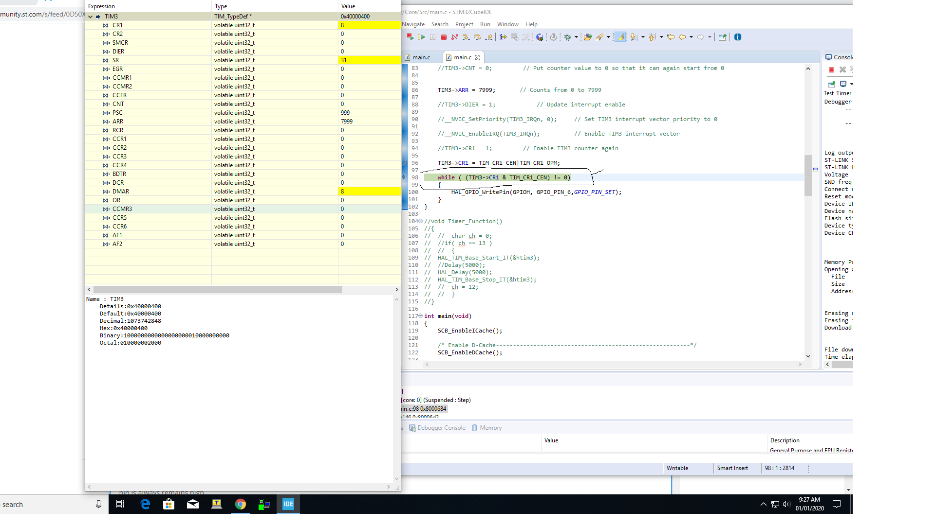
TIM3->CR1 = TIM_CR1_CEN|TIM_CR1_OPM;
while ( (TIM3->CR1 & TIM_CR1_CEN) != 0)
{
HAL_GPIO_WritePin(GPIOH, GPIO_PIN_6,GPIO_PIN_SET);
}
Best Regards
Dipak Garasiya
Options
- Mark as New
- Bookmark
- Subscribe
- Mute
- Subscribe to RSS Feed
- Permalink
- Email to a Friend
- Report Inappropriate Content
2019-12-31 04:31 AM
How do you know that CEN does not get cleared? What do TIM3 registers contain when you let it run for a while and stop it? Does it exit the loop?
Options
- Mark as New
- Bookmark
- Subscribe
- Mute
- Subscribe to RSS Feed
- Permalink
- Email to a Friend
- Report Inappropriate Content
2019-12-31 08:00 PM
I have checked by debugging code , while loop never exits. and stops code there
i have attached my debugging sceenshot where you will get TIM3 register value at timer of entering while loop
Best Regards
Dipak Garasiya
Options
- Mark as New
- Bookmark
- Subscribe
- Mute
- Subscribe to RSS Feed
- Permalink
- Email to a Friend
- Report Inappropriate Content
2020-01-02 01:46 AM
I can't see the screenshot.
Check the timer registers. Do PSC, ARR and CR1 contain the values you've set? Is the counter changing?
Options
- Mark as New
- Bookmark
- Subscribe
- Mute
- Subscribe to RSS Feed
- Permalink
- Email to a Friend
- Report Inappropriate Content
2020-01-02 05:08 AM
What's *after* the while loop?
Put some code there, e.g. another write to a GPIO pin.
JW
Options
- Mark as New
- Bookmark
- Subscribe
- Mute
- Subscribe to RSS Feed
- Permalink
- Email to a Friend
- Report Inappropriate Content
2020-01-02 08:27 PM
Related Content
- STM32CubeIDE crashes - Problem: EXC_BAD_ACCESS (SIGABRT) in STM32CubeIDE (MCUs)
- FDCAN Not working oh H755zi in STM32 MCUs Boards and hardware tools
- i can't erase flash memory of STM32C0116DK in Other tools (MCUs)
- Assigning LPUART to specific clock for STM32L071K8U6 in STM32 MCUs products
- Issue with mbedTLS Handshake Failure When Using HyperRAM for FreeRTOS Heap in STM32 MCUs Security