Turn on suggestions
Auto-suggest helps you quickly narrow down your search results by suggesting possible matches as you type.
Showing results for
- STMicroelectronics Community
- STM32 MCUs
- STM32 MCUs Embedded software
- CMSIS DSP FFT library harmonics level measurement
Options
- Subscribe to RSS Feed
- Mark Topic as New
- Mark Topic as Read
- Float this Topic for Current User
- Bookmark
- Subscribe
- Mute
- Printer Friendly Page
CMSIS DSP FFT library harmonics level measurement
Options
- Mark as New
- Bookmark
- Subscribe
- Mute
- Subscribe to RSS Feed
- Permalink
- Email to a Friend
- Report Inappropriate Content
2019-10-09 11:20 PM
I tried to use CMSIS DSP library for FFT implementation on STM32F407. I based my project on Tilen MaJerle library.
I sample data with on board ADC and fill the input buffer with function TM_FFT_AddToBuffer(TM_FFT_F32_t* FFT, float32_t sampleValue). Hereafter I process data with function TM_FFT_Process_F32(TM_FFT_F32_t* FFT).
uint8_t TM_FFT_AddToBuffer(TM_FFT_F32_t* FFT, float32_t sampleValue) {

    /* Check if memory available */
    if (FFT->Count < FFT->FFT_Size) {
       /* Add to buffer, real part */
       FFT->Input[2 * FFT->Count] = sampleValue;

       /* Imaginary part set to 0 */
       FFT->Input[2 * FFT->Count + 1] = 0;

       /* Increase count */
       FFT->Count++;
    }

    /* Check if buffer full */
    if (FFT->Count >= FFT->FFT_Size) {
        /* Buffer full, samples ready to be calculated */
        return 1;
     }

     /* Buffer not full yet */
    return 0;
}


void TM_FFT_Process_F32(TM_FFT_F32_t* FFT) {

    uint16_t iCntr = 0;
    float coeff = 2.0*0.7071067812/(float)(FFT->FFT_Size);

    /* Process FFT input data */
    arm_cfft_f32(FFT->S, FFT->Input, 0, 1);

    /* Process the data through the Complex Magniture Module for calculating the magnitude at each bin */
    arm_cmplx_mag_f32(FFT->Input, FFT->Output, FFT->FFT_Size);

    for (iCntr = 1; iCntr < (FFT->FFT_Size); iCntr++)
         FFT->Output[iCntr] *= coeff; //high-order harmonics values - magnitude

    FFT->Output[0] /= (float)FFT->FFT_Size; //dc component value

    /* Reset count */
    FFT->Count = 0;

}
I added some simple transformations in TM_FFT_Process_F32 aimed to harmonics level adjustment. Of course, when I exclude them and use original Tilen code I get the same result.
As you see, I tried arm_cfft_f32(…) and arm_cmplx_mag_f32(…) functions. I also tried arm_rfft_fast_f32(…) function for my purposes and got the same result.
My problem is magnitude calculation accuracy. My task expects to get accurate level calculations of predetermined harmonics. I measure clear sinusoidal AC signal with DC offset on the ADC input with voltmeter. Then I measure the signal frequency with FFT lib and get the signal level degradation with the frequency increase. I take into account restrictions regarding the maximum measured frequency for the given sampling rate and that fact, I can't use more than 4096 samples with CMSIS DSP FFT.
I also need small frequency step, e.g., 1 Hz for the range between 100 and 1000 Hz.
There I show you the results. Blue line is measured with AC voltmeter. Red line is my measurements with FFT library. Sampling rate 4096 Hz, number of samples – 4096. By the way, the frequency is measured with some error. 100 Hz is defined as 101Hz, 800 Hz – as 808Hz. But this doesn't confuse me much.

The same picture is attained for other frequency ranges and sampling rates.
Now I see the only head-on decision is to mathematically adjust my results to real measured values. But this is not an elegant solution. It's highly likely that I neglect some important features of DSP FFT analysis and lack understanding of the math algorithm.
Other FFT realizations are not so clear to me. And does it really make sense to use other libs, for example, kissFFT and so on? Who has proven experience with other libs and would be kind to share his view with me? Any piece of advice is highly appreciated.
Solved! Go to Solution.
Labels:
- Labels:
-
CMSIS
-
DSP
-
STM32F4 Series
1 ACCEPTED SOLUTION
Accepted Solutions
Options
- Mark as New
- Bookmark
- Subscribe
- Mute
- Subscribe to RSS Feed
- Permalink
- Email to a Friend
- Report Inappropriate Content
2020-04-21 12:04 PM
Dear friends. Thanks a lot for your answers. But at last I struggled my issue myself😀 And about half a year it took me to sit down and write about the solution here.
For my own part, it was quite a negligent misconception of how FFT works. There is a feature consisting in that fact that the energy of the given signal is spread between the given frequency and some nearby frequencies. So if we take the magnitude of the signal at the given frequency from the results of DSP library Fourier calculation, of course, we’ll get the signal loss which increases with increase of the operating frequency at the given sample rate. But if we take the root mean square value of the magnitudes of the given frequency and of some nearby frequencies, we’ll get no signal loss.
I studied DSP accuracy capabilities in practice – for different sample rates and for the range of frequencies between 30 Hz and 32 kHz. There is a calculable frequency dispersion in which we should calculate our signal magnitude as a root mean square value of the magnitudes of the frequencies inside the dispersion. And there is a calculable frequency definition error. The higher the sample rate, the farther is the calculated value of the signal frequency. By the calculated signal frequency we mean the frequency for which we see the magnitude maximum (when observing a clear sinusoidal signal). But the frequency shift is predictable and doesn’t make any problem. The more important property is signal spreading. If we take it into account and calculate the signal magnitude more thoroughly it will give us excellent results. Mine are that now my calculations finely coincide with voltmeter GVT-measurements in dBm. The difference is not more than 2% in the range of -40 … +22 dBm, for frequencies (30Hz…32kHz).
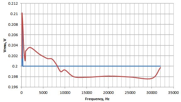
Here there're some results of magnitude calculation via a wide frequency range with voltage level 0,2Vrms. Blue line is measured with AC voltmeter. Red line is my measurements with FFT library. Number of samples – 4096 and sampling rate differs for special frequency sub-ranges. It is 4096 Hz for F=(30…1024)Hz, 20480 Hz for F=(1024…4096)Hz, 40960 Hz for F=(4096…8192)Hz and 81920 Hz for F=(8192…32000)Hz. As you see, the results are very satisfying.

I believe that for the people who are at their best with mathematical basics of Fourier transform my case is quite a simple task. But maybe I didn’t get the basics at once and too much reckoned on the DSP library calculation capabilities, so I’ve lost some time and nerve resources on the issue described. But now it’s OK and I’m deeply satisfied with DSP FFT realization.
5 REPLIES 5
Options
- Mark as New
- Bookmark
- Subscribe
- Mute
- Subscribe to RSS Feed
- Permalink
- Email to a Friend
- Report Inappropriate Content
2019-10-10 12:05 AM
> And does it really make sense to use other libs, for example, kissFFT and so on? Who has proven experience with other libs and would be kind to share his view with me? Any piece of advice is highly appreciated.
It is some while ago when I dabbled with FFT code, but I suppose other libs would not immediately solve your problem.
I think it is precision related. Single precision (float) has just 24 bit mantissa, which is not really much.
The CMSIS FFT code - and other libs presumably - are designed for real-time usage, i.e. use builtin data types and sizes (float is supported by the FPU).
With dropping the real-time requirement, you could port a double precision algorithm, and reducing the added-up errors.
Options
- Mark as New
- Bookmark
- Subscribe
- Mute
- Subscribe to RSS Feed
- Permalink
- Email to a Friend
- Report Inappropriate Content
2019-10-10 12:28 AM
I see, you are right. But if we put aside the real-time requirement (anyway I measure AC signal and then FFT process the data and wait for the result about a second or so on) what techniques would you recommend me? The point is for them to be applicable to STM32F4.
Options
- Mark as New
- Bookmark
- Subscribe
- Mute
- Subscribe to RSS Feed
- Permalink
- Email to a Friend
- Report Inappropriate Content
2019-10-10 05:19 AM
You can port double-based Fourier transform code as well, no problem. I know of no toolchain that comes without proper double emulation code.
Since the Cortex M FPU does neither supports trigonometric functions (sin/cos) directly, nor double operations, the runtime impact might be one order of magnitude.
I used the FFTW lib some while ago, which is PC based. But that lib contained a lot of optimization towards x86 processors, and is hardly portable.
When dealing with (non-commercial) applications dealing with audio and spectral data, I used a PC (Linux) with audio card for higher precision, and Cortex M4 based boards for portable real-time. Never had the need for high precision on MCUs, the CMSIS did sufficiently well for me.
Not sure if a Cortex A / Linux-based hardware could fit you application.
Options
- Mark as New
- Bookmark
- Subscribe
- Mute
- Subscribe to RSS Feed
- Permalink
- Email to a Friend
- Report Inappropriate Content
2019-12-02 06:08 PM
1. Sampling rate should be greater than 10 times the sample frequency for proper amplitude fidelity
2. The FFT processing time is less than the sampling time of a single frame sample, which can ensure real-time performance
3. For FFT support over 4096 points, I am also looking for other FFT LIB
Options
- Mark as New
- Bookmark
- Subscribe
- Mute
- Subscribe to RSS Feed
- Permalink
- Email to a Friend
- Report Inappropriate Content
2020-04-21 12:04 PM
Dear friends. Thanks a lot for your answers. But at last I struggled my issue myself😀 And about half a year it took me to sit down and write about the solution here.
For my own part, it was quite a negligent misconception of how FFT works. There is a feature consisting in that fact that the energy of the given signal is spread between the given frequency and some nearby frequencies. So if we take the magnitude of the signal at the given frequency from the results of DSP library Fourier calculation, of course, we’ll get the signal loss which increases with increase of the operating frequency at the given sample rate. But if we take the root mean square value of the magnitudes of the given frequency and of some nearby frequencies, we’ll get no signal loss.
I studied DSP accuracy capabilities in practice – for different sample rates and for the range of frequencies between 30 Hz and 32 kHz. There is a calculable frequency dispersion in which we should calculate our signal magnitude as a root mean square value of the magnitudes of the frequencies inside the dispersion. And there is a calculable frequency definition error. The higher the sample rate, the farther is the calculated value of the signal frequency. By the calculated signal frequency we mean the frequency for which we see the magnitude maximum (when observing a clear sinusoidal signal). But the frequency shift is predictable and doesn’t make any problem. The more important property is signal spreading. If we take it into account and calculate the signal magnitude more thoroughly it will give us excellent results. Mine are that now my calculations finely coincide with voltmeter GVT-measurements in dBm. The difference is not more than 2% in the range of -40 … +22 dBm, for frequencies (30Hz…32kHz).
Here there're some results of magnitude calculation via a wide frequency range with voltage level 0,2Vrms. Blue line is measured with AC voltmeter. Red line is my measurements with FFT library. Number of samples – 4096 and sampling rate differs for special frequency sub-ranges. It is 4096 Hz for F=(30…1024)Hz, 20480 Hz for F=(1024…4096)Hz, 40960 Hz for F=(4096…8192)Hz and 81920 Hz for F=(8192…32000)Hz. As you see, the results are very satisfying.
I believe that for the people who are at their best with mathematical basics of Fourier transform my case is quite a simple task. But maybe I didn’t get the basics at once and too much reckoned on the DSP library calculation capabilities, so I’ve lost some time and nerve resources on the issue described. But now it’s OK and I’m deeply satisfied with DSP FFT realization.
Related Content
- library and example experience comparible to the Arduino IDE in STM32CubeIDE (MCUs)
- Issues using CMSIS Inverse FFT on STM32 in STM32 MCUs products
- TSL library stateIDs in STM32 MCUs products
- Unexpected UART timeout error HAL_TIMEOUT with the STM32G0B1RET MCU in STM32 MCUs products
- X-CUBE-CLASSB-U5(STL) issue(Hardfault) of TM7 test executing in ThreadX in STM32 MCUs products