Turn on suggestions
Auto-suggest helps you quickly narrow down your search results by suggesting possible matches as you type.
Showing results for
- STMicroelectronics Community
- STM32 MCUs
- STM32 MCUs products
- arbitrary waveform using DMA and timer
Options
- Subscribe to RSS Feed
- Mark Topic as New
- Mark Topic as Read
- Float this Topic for Current User
- Bookmark
- Subscribe
- Mute
- Printer Friendly Page
arbitrary waveform using DMA and timer
Options
- Mark as New
- Bookmark
- Subscribe
- Mute
- Subscribe to RSS Feed
- Permalink
- Email to a Friend
- Report Inappropriate Content
2019-03-26 08:37 AM
Hello,
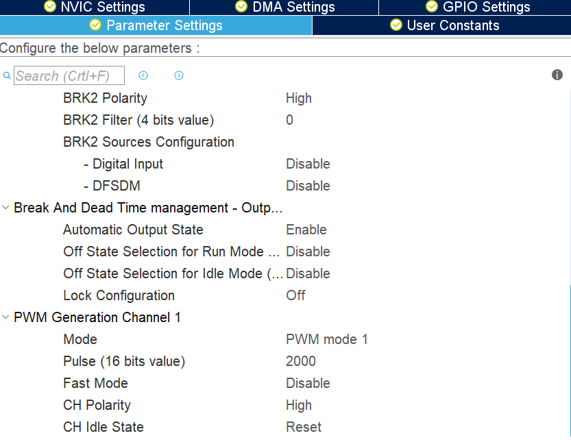
i am trying to generate arbitrary waveform. But it still dose not work. I think it's up to the configuration. I have created a array of 6 words for two waveform patterns to be send to TIM1 channel 1 (TIM1_ARR, TIM1_RCR, TIM1_CCR1) This is how the basics look
uint32_t aSRC_Buffer[6] = { 2000,1,800,3000,2,200}; /// ARR, RCR, CCR1 x 2. But i am just getting a 3.3 V on the PIN.
uint32_t aSRC_Buffer[6] = { 2000,1,800,3000,2,200};


HAL_TIM_DMABurst_WriteStart(&htim1,TIM_DMABASE_ARR, TIM_DMA_TRIGGER,
(uint32_t *)aSRC_Buffer, TIM_DMABURSTLENGTH_3TRANSFERS);#DMA #DMA #TIMER
7 REPLIES 7
Options
- Mark as New
- Bookmark
- Subscribe
- Mute
- Subscribe to RSS Feed
- Permalink
- Email to a Friend
- Report Inappropriate Content
2019-03-26 09:59 AM
Perform the writes to those registers "manually". Does the pin voltage change?
jW
Options
- Mark as New
- Bookmark
- Subscribe
- Mute
- Subscribe to RSS Feed
- Permalink
- Email to a Friend
- Report Inappropriate Content
2019-03-26 10:25 AM
@Community member the pin is high because i have set the GPIO Mode to Pull-up
Options
- Mark as New
- Bookmark
- Subscribe
- Mute
- Subscribe to RSS Feed
- Permalink
- Email to a Friend
- Report Inappropriate Content
2019-03-26 05:19 PM
Well, if you set it to pull up (and presumably as Input?) and you find it high, then it works exactly according to your setting, doesn't it?
What's the problem then?
JW
Options
- Mark as New
- Bookmark
- Subscribe
- Mute
- Subscribe to RSS Feed
- Permalink
- Email to a Friend
- Report Inappropriate Content
2019-03-27 05:31 AM
i am trying to generate Waveform Pattern with DMA and Timer. the DMA should send the Data to the TIM1_CH1. but it dose not work. Somehow i dont see the DMA configuration in the main.c i do not know why. i just can see the following:
static void MX_DMA_Init(void)
{
  /* DMA controller clock enable */
  __HAL_RCC_DMA2_CLK_ENABLE();

  /* DMA interrupt init */
  /* DMA2_Stream5_IRQn interrupt configuration */
  HAL_NVIC_SetPriority(DMA2_Stream5_IRQn, 0, 0);
  HAL_NVIC_EnableIRQ(DMA2_Stream5_IRQn);

}Options
- Mark as New
- Bookmark
- Subscribe
- Mute
- Subscribe to RSS Feed
- Permalink
- Email to a Friend
- Report Inappropriate Content
2019-03-27 05:32 AM
HAL_TIM_Base_Start(&htim1);
HAL_TIM_PWM_Start(&htim1,TIM_CHANNEL_1);
HAL_TIM_DMABurst_WriteStart(&htim1,TIM_DMABASE_ARR,TIM_DMA_UPDATE,
(uint32_t *)aSRC_Buffer, TIM_DMABURSTLENGTH_3TRANSFERS);Options
- Mark as New
- Bookmark
- Subscribe
- Mute
- Subscribe to RSS Feed
- Permalink
- Email to a Friend
- Report Inappropriate Content
2019-03-27 02:37 PM
Start with getting PWM output on that pin, without DMA.
JW
Options
- Mark as New
- Bookmark
- Subscribe
- Mute
- Subscribe to RSS Feed
- Permalink
- Email to a Friend
- Report Inappropriate Content
2019-03-27 07:46 PM
If you want to generate a burst of pulses of different timings on a pin, you select a Timer which can be DMA access for its CHANNEL register. Create the toggle points over the course of a timer period and feed this toggle timestamps cyclically to the channel output compare as toggle point.
The timer period should remain fixed.
Related Content
- NEED AN ADVICE FOR NEW PROJECT in STM32 MCUs products
- HSE oscillator not running on NUCLEO-H753ZI board in STM32 MCUs Boards and hardware tools
- STM32H7 ADC DAC Timer in STM32 MCUs Boards and hardware tools
- STM32F3348-DISCO HRTIM DMA PWM Sine Wave in STM32 MCUs products
- STM32H7 TIM12 TRGO DAC DMA syncronization in STM32 MCUs products