Turn on suggestions
Auto-suggest helps you quickly narrow down your search results by suggesting possible matches as you type.
Showing results for
- STMicroelectronics Community
- STM32 MCUs
- STM32 MCUs TouchGFX and GUI
- DSI custom board problem with STM32F769BI MCU
Options
- Subscribe to RSS Feed
- Mark Topic as New
- Mark Topic as Read
- Float this Topic for Current User
- Bookmark
- Subscribe
- Mute
- Printer Friendly Page
DSI custom board problem with STM32F769BI MCU
Options
- Mark as New
- Bookmark
- Subscribe
- Mute
- Subscribe to RSS Feed
- Permalink
- Email to a Friend
- Report Inappropriate Content
2019-02-28 10:30 AM
Hello,
I used STM32F769I-EVAL board as a design reference for custom board. However, I could not achieve correct operation of MB1166 LCD board
which is connected via DSI. It works well on the evaluation board.
When MCU tryies to display a picture, screen fickers with coloured lines and stays white.
Theres some hardware problem which I cannot figure out. Im attaching custom board schematics of DSI peripheral. STM32F769BIT6 MCU is used.
Any help to debug such issue would be apriciated.
Labels:
- Labels:
-
DSI
-
STM32F7 Series
16 REPLIES 16
Options
- Mark as New
- Bookmark
- Subscribe
- Mute
- Subscribe to RSS Feed
- Permalink
- Email to a Friend
- Report Inappropriate Content
2019-02-28 05:43 PM
Schematics looks fine at first glance, did you double check layout for footprints missmatch and doubled check the differential pairs for proper routing?
Options
- Mark as New
- Bookmark
- Subscribe
- Mute
- Subscribe to RSS Feed
- Permalink
- Email to a Friend
- Report Inappropriate Content
2019-02-28 09:55 PM
Dear Du,
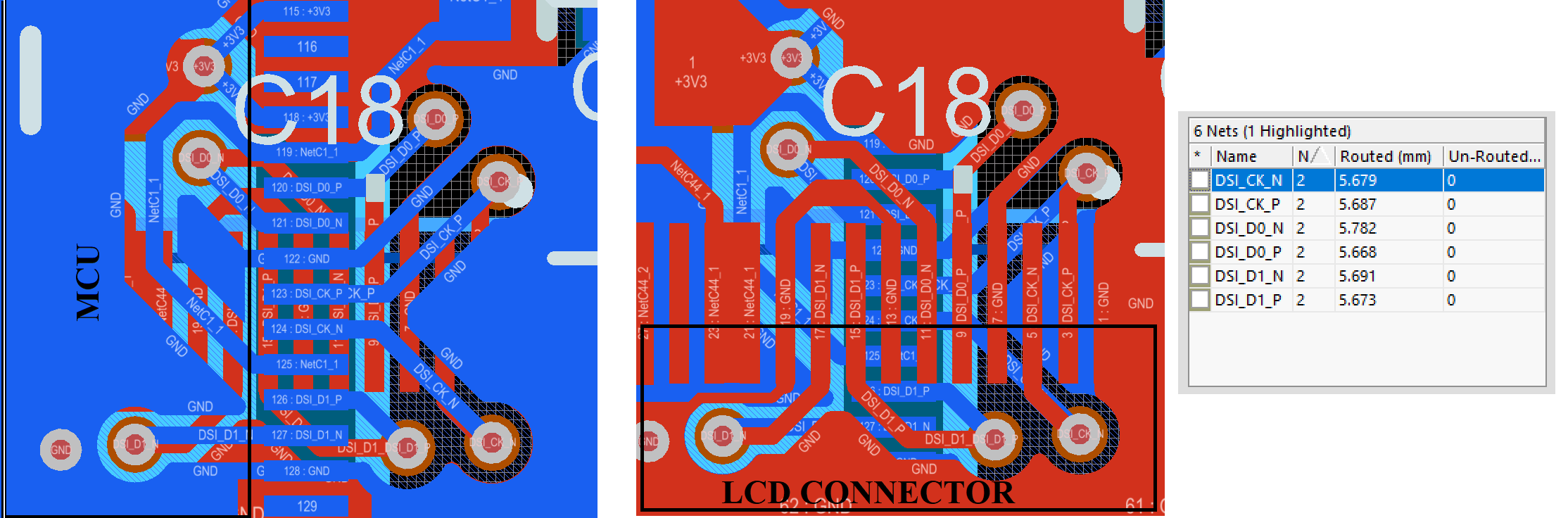
footprints are correct. I figured that DSI routing could have been a problem on my first PCB design. So this time I designed around the DSI. My approach was to reduce length of DSI route as short as possible while maintaining DSI_CK, DSI_D0 and DSI_D1 lengths as equal as possible.
Im attaching PCB routing of DSI connection and DSI net lengths.
Options
- Mark as New
- Bookmark
- Subscribe
- Mute
- Subscribe to RSS Feed
- Permalink
- Email to a Friend
- Report Inappropriate Content
2019-02-28 10:17 PM
Did your code have any change? Any IO remapping or reconfigurations? What else have you checked through so far that you could rule out for sure?
>
>
Options
- Mark as New
- Bookmark
- Subscribe
- Mute
- Subscribe to RSS Feed
- Permalink
- Email to a Friend
- Report Inappropriate Content
2019-03-01 02:42 AM
Code was not changed. I upload the same hex file through STM32 ST-LINK Utility. It works on evaluation board and does not on custom board.
Disconnected lcd screens from both boards and checked if signals and voltage levels of LCD connector pins are the same. It was ok and pins were not mixed. Only difference was that at on the discovery boards pin LCD connections 37 pin was high. However, on LCD MB1166 board this pin was disconnected so it should not be the source of the issue.
Checked crystal oscilators frequency - 25 MHz same as on evaluation board. I captured signals of DSI channels from custom board. Cold you check if it looks ok, because D1 signals look suspicious.
Im using new MCU. Does it need any specific configuration before uploading the code to flash?
Options
- Mark as New
- Bookmark
- Subscribe
- Mute
- Subscribe to RSS Feed
- Permalink
- Email to a Friend
- Report Inappropriate Content
2019-03-01 11:13 PM
Can you capture the first 500mS of activity on the eval board and then the custom board and compare the two oscope shots to each other?
I don't have the datasheet for the LCD board, does that LCD use D1 channel?
Are you using the same part numbers for the crystals and any other clock related sources?
Options
- Mark as New
- Bookmark
- Subscribe
- Mute
- Subscribe to RSS Feed
- Permalink
- Email to a Friend
- Report Inappropriate Content
2019-03-02 03:59 AM
LCD boards datasheet: https://www.st.com/content/ccc/resource/technical/document/user_manual/group0/10/0d/a5/a2/7e/b9/4c/ca/DM00321394/files/DM00321394.pdf/jcr:content/translations/en.DM00321394.pdf
Yes, it should use D1 channel. I will capture CLK, D0,D1 and TE signals in few upcoming days.
Crystal oscillators part numbers are different, however parameters are the same. I double checked amplitude and frequency with the oscilloscope of both boards.
Options
- Mark as New
- Bookmark
- Subscribe
- Mute
- Subscribe to RSS Feed
- Permalink
- Email to a Friend
- Report Inappropriate Content
2019-03-02 06:39 AM
Perhaps have an ST FAE review the PCB and trace layout/lengths, circuit performance likely to be critical at these speeds.
Tips, Buy me a coffee, or three.. PayPal Venmo
Up vote any posts that you find helpful, it shows what's working..
Up vote any posts that you find helpful, it shows what's working..
Options
- Mark as New
- Bookmark
- Subscribe
- Mute
- Subscribe to RSS Feed
- Permalink
- Email to a Friend
- Report Inappropriate Content
2019-03-05 02:45 AM
Dear Du,
I attached eval board and custom boards DSI signals. Captured oscilograms are from MB1166 LCD side.
Data signals seems to be fine.
Im uploading hex file from "STM32F769I_EVAL\Applications\Display\LCD_DSI_ImagesSlider" example. It uses DSI LCD screen and external QSPI flash which is placed on my custom board. Hex successfully flashes. I also tried applications which does not used external flash. The issue remains.
Do you have any other suggestions? Ill try to sample and compare more signals from LCD side.
Options
- Mark as New
- Bookmark
- Subscribe
- Mute
- Subscribe to RSS Feed
- Permalink
- Email to a Friend
- Report Inappropriate Content
2019-03-05 02:47 AM
Dear Clive Two.Zero,
I will try to contact them through the supplier of the evaluation board.
Related Content
- STM32F405 Can not connect to target in STM32 MCUs products
- [STM32H563] NetXDuo TCP Echo Server only working in Debug mode (fixed IP address) in STM32 MCUs Embedded software
- GPU2D hangup on STM32H7S78-DK in STM32 MCUs TouchGFX and GUI
- STM32H735-DK: SMPS vs LDO interesting observation in STM32 MCUs products
- VSCode GDB Debug - Enable Watchdog Halt in STM32 MCUs Embedded software