Turn on suggestions
Auto-suggest helps you quickly narrow down your search results by suggesting possible matches as you type.
Showing results for
- STMicroelectronics Community
- STM32 MCUs
- STM32 MCUs Embedded software
- USB DFU not working on bare metal stm32. Not showi...
Options
- Subscribe to RSS Feed
- Mark Topic as New
- Mark Topic as Read
- Float this Topic for Current User
- Bookmark
- Subscribe
- Mute
- Printer Friendly Page
USB DFU not working on bare metal stm32. Not showing the MCU via usb
Options
- Mark as New
- Bookmark
- Subscribe
- Mute
- Subscribe to RSS Feed
- Permalink
- Email to a Friend
- Report Inappropriate Content
2019-02-27 02:58 PM

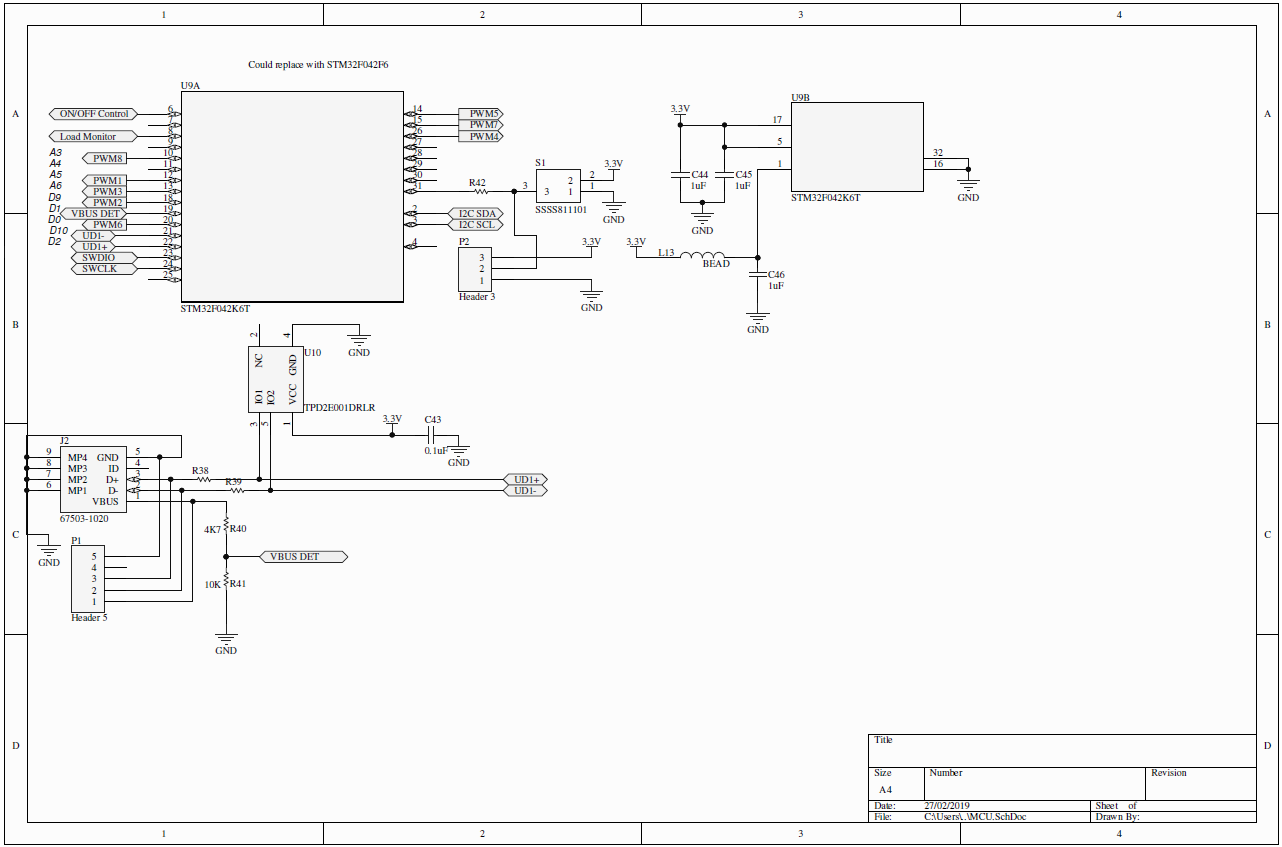
I can not get DFU to work in the schematic shown.
I am attempting to enter DFU mode but I can't see any devices in Win 7.
I don't know if this is a USB issue or DFU mode issue.
I would appreciate any help.
Best
Nick
Labels:
- Labels:
-
Bootloader
-
RESET
-
STM32F0 Series
14 REPLIES 14
Options
- Mark as New
- Bookmark
- Subscribe
- Mute
- Subscribe to RSS Feed
- Permalink
- Email to a Friend
- Report Inappropriate Content
2019-02-27 09:05 PM
For your package of the CPU, review the location and use of the BOOT0 pin which is required to invoke the use of the USB DFU.
Review the following as a good read:
https://robo.fish/wiki/index.php?title=Programming_STM32F042
Download and install STM DFuse:
https://www.st.com/en/development-tools/stsw-stm32080.html
Once you satisfy the condition for BOOT0 (and perhaps BOOT1 if applied on this CPU) AND pulse #RESET, then the USB DFU will boot.
Post back with your update.
Options
- Mark as New
- Bookmark
- Subscribe
- Mute
- Subscribe to RSS Feed
- Permalink
- Email to a Friend
- Report Inappropriate Content
2019-02-28 02:33 AM
Are we sure the part in question supports DFU in ROM. How large is the ROM?
Tips, Buy me a coffee, or three.. PayPal Venmo
Up vote any posts that you find helpful, it shows what's working..
Up vote any posts that you find helpful, it shows what's working..
Options
- Mark as New
- Bookmark
- Subscribe
- Mute
- Subscribe to RSS Feed
- Permalink
- Email to a Friend
- Report Inappropriate Content
2019-02-28 03:23 AM
Hi, I have done as Mon2 says, double checked everything and unfortunately I can't get it to work. I think its must be a schematic issue which I am trying to solve now.
Clive - The DFU for this part is in ROM - at least it says so in the STM32F042K6 datasheet.
Options
- Mark as New
- Bookmark
- Subscribe
- Mute
- Subscribe to RSS Feed
- Permalink
- Email to a Friend
- Report Inappropriate Content
2019-02-28 05:34 AM
This part actually boots in DFU mode also if there is no valid program in flash (at least it does for the TSSOP20 version, which doesn't have BOOT0 pin). The serial resistors are not needed on the USB lines, try to see if changing them to 0R fixes the issue.
Options
- Mark as New
- Bookmark
- Subscribe
- Mute
- Subscribe to RSS Feed
- Permalink
- Email to a Friend
- Report Inappropriate Content
2019-02-28 05:57 AM
Thanks for the confirmation Ben
Tips, Buy me a coffee, or three.. PayPal Venmo
Up vote any posts that you find helpful, it shows what's working..
Up vote any posts that you find helpful, it shows what's working..
Options
- Mark as New
- Bookmark
- Subscribe
- Mute
- Subscribe to RSS Feed
- Permalink
- Email to a Friend
- Report Inappropriate Content
2019-02-28 06:10 AM
Also, USB typically demands impedance controlled traces for the USB lines between the USB connector and the USB CPU pins. About 90 ohms. Was this done?
Concerned also about P1 being mated with the USB connector which is usually not recommended unless special care was taken on the PCB layout as this will throw off the USB line impedance. There are many notes on how USB layout should be performed for best results.
However, you may be still ok here as the USB boot loader operates at 12 Mbps (FS) and not HS (480 Mbps) so you may be able to get this to still function yet. However, you may also face flaky results due to these flyers of the USB traces.
To confirm, you are strapping BOOT0 to a logic HIGH and then power cycling the board for a proper RESET of the CPU?
Is the USB cable being used "fully loaded" that offers the D+ / D- lines? If in doubt, grab another and test again. We have been stung with some garbage "charge ONLY" cables where only Vbus and Ground pins are present. Someone must have saved 5 cents somewhere, perhaps Lucy.

---
Update - why is PIN 4 floating? That is #RST for the CPU.
Does that pin not require a RC circuit for a power on reset?
R to +3v3
C to ground
Common to #RST pin 4.
Please confirm.
Options
- Mark as New
- Bookmark
- Subscribe
- Mute
- Subscribe to RSS Feed
- Permalink
- Email to a Friend
- Report Inappropriate Content
2019-02-28 07:42 AM
>>Does that pin not require a RC circuit for a power on reset?
Technically I don't think it does. I has an internal pull-up if I recall, and a POR circuit with minimal pulse-width attached via VDDA. People tend to use RC implementations to slow the rise of NRST
Tips, Buy me a coffee, or three.. PayPal Venmo
Up vote any posts that you find helpful, it shows what's working..
Up vote any posts that you find helpful, it shows what's working..
Options
- Mark as New
- Bookmark
- Subscribe
- Mute
- Subscribe to RSS Feed
- Permalink
- Email to a Friend
- Report Inappropriate Content
2019-02-28 08:57 AM
>>Also, USB typically demands impedance controlled traces for the USB lines between the USB connector and the USB CPU pins. About 90 ohms. Was this done?
It is integrated in the chip, it is stated in the datasheet. That's why I wrote that 0R resistors should be used in serial.
Options
- Mark as New
- Bookmark
- Subscribe
- Mute
- Subscribe to RSS Feed
- Permalink
- Email to a Friend
- Report Inappropriate Content
2019-02-28 09:35 PM
Hi,
I changed USB serial resistors to 0R. The pull up resistor for D+ is supposedly integrated internally into the chip, however the D+ is at 0V as well as D-.
I am putting BOOT0 high and resetting.
I checked different cables and checked them with other devices and picked the ones that work with other devices so this should not be an issue.
P1 is unconnected to a header but I am using it as test points. I thought for USB FS it will be enough as P1 is very close.
Regarding the NRST i left it unconnected as it has an internal pull up resistor.
Still can't get it to work...
I really appreciate all your help.
Related Content
- uds protocol in STM32 MCUs Embedded software
- Working with STM32 is so frustrating in STM32 MCUs products
- USB project example in STM32 MCUs products
- can Ewarm project be opened in Keil or CubeIDE ? in STM32 MCUs Boards and hardware tools
- Error unable to locate device in STM32 MCUs Boards and hardware tools