Turn on suggestions
Auto-suggest helps you quickly narrow down your search results by suggesting possible matches as you type.
Showing results for
- STMicroelectronics Community
- STM32 MCUs
- STM32 MCUs products
- Can I leave some VDD / VSS pins unconnected?
Options
- Subscribe to RSS Feed
- Mark Topic as New
- Mark Topic as Read
- Float this Topic for Current User
- Bookmark
- Subscribe
- Mute
- Printer Friendly Page
Can I leave some VDD / VSS pins unconnected?
Options
- Mark as New
- Bookmark
- Subscribe
- Mute
- Subscribe to RSS Feed
- Permalink
- Email to a Friend
- Report Inappropriate Content
2015-12-27 10:15 PM
Posted on December 28, 2015 at 07:15
First, I'm aware from the
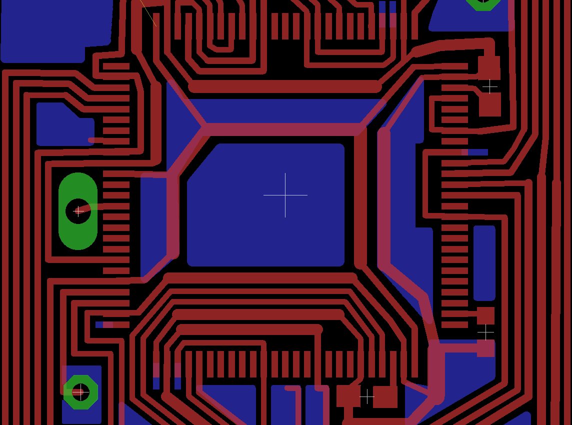
that connecting all power supply pins is required for all practical purposes and that even if skipping some seems to work, there eventually could be subtle failures. But my home made circuit board is facing severe routing challenges since it only has 1 layer. I've already resorted to creating many circuitous routes to deal with the limitations of 2D routing. Just look at the maze of wires.Although I'm amazed at how much you can do with just 1 layer, I still need to solder on ~5 jumpers. I'm tempted to reduce them by omitting some power supply connections. Probing the power pins on a STM32F4 Discovery board, it seems all the VSS and VDD pins are internally connected, so leaving some unconnected seems a possibility. I haven't checked for an unsoldered chip, which could prove otherwise.Here are my circumstances:1. The MCU doesn't do any analog processing or analog I/O - only digital. It seems digital should be more robust against voltage variations (50mV max according to datasheet). I know the internal RC oscillator is powered by the analog supply, so leaving VddA/VssA unconnected is out of the question.2. total current use is right around 100mA. According to the datasheet, even 1 pin can provide this amount of current. There is 1 LED that blinks momentarily that could add ~20mA.On the STM32F7 QFP 100 package I'm using, there's at least 1 pair of VDD/VSS on each of the 4 sides, which makes sense since that would ensure any part of the chip would be within a certain distance from a VDD/VSS pair.On the edge with pins 26-50, there are 2 pairs of VDD/VSS, so it seems getting rid of 1 pair will do the least harm.Has anyone else been in my situation and attempted this? Anyone want to advise against this or give a tentative approval? #stm32f7
Labels:
- Labels:
-
STM32F7 Series
3 REPLIES 3
Options
- Mark as New
- Bookmark
- Subscribe
- Mute
- Subscribe to RSS Feed
- Permalink
- Email to a Friend
- Report Inappropriate Content
2015-12-28 01:00 AM
Posted on December 28, 2015 at 10:00
Can you do fix a nonfunctional CPU board?
The best way IMO to try something like this, is to build it correctly first, and when it works then start experimenting these kind of things. But must importantly. Seedstudio and Itead (and others) make good quality 10*10cm PC boards at around 20 $£€ per 10 pieces. Why would anyone make their own boards anymore. Arduino forum has a list of low cost PCB manufacturers, there could be others.Options
- Mark as New
- Bookmark
- Subscribe
- Mute
- Subscribe to RSS Feed
- Permalink
- Email to a Friend
- Report Inappropriate Content
2015-12-28 07:46 PM
Posted on December 29, 2015 at 04:46
Yeah, making PCBs with 0.5mm wire pitches is a losing battle I admit. The only reason I've been holding out is because of the perceived learning curve (all those software, file formats, and design rules) and uncertain manual quotes. I have been using Eagle for > 1 year. Apparently it's not that difficult to save as Gerber instead of printing the photomask on a transparency and making it yourself.
I've didn't know Seeed had a PCB service. I only knew about Advanced Circuits, which is more expensive. Thanks, I'll definitely give them a try.Yes, I've already have a manually built board working, but it's finicky even with all the power pins connected. It works for a few weeks before suddenly experiencing a short circuit or signal integrity issues. Probably because there's no solder mask.Options
- Mark as New
- Bookmark
- Subscribe
- Mute
- Subscribe to RSS Feed
- Permalink
- Email to a Friend
- Report Inappropriate Content
2015-12-29 04:50 AM
Posted on December 29, 2015 at 13:50
So you already know Eagle. Then I don't think it is difficult to learn the rest. I havn't used it myself but I quess it has an autorouter. That is a bonus when you can use vias freely.
I have bought only from Itead, and I think that they have settings or script for Eagle or something, so you only need to design a normal 2-layer board. (There are 4-layer boards, too for extra cost.) Those same settings are probably good for others too. Have fun Leif
Related Content