Turn on suggestions
Auto-suggest helps you quickly narrow down your search results by suggesting possible matches as you type.
Showing results for
- STMicroelectronics Community
- STM32 MCUs Software development tools
- STM32CubeMX (MCUs)
- Possible HAL F429 UART TX Bug
Options
- Subscribe to RSS Feed
- Mark Topic as New
- Mark Topic as Read
- Float this Topic for Current User
- Bookmark
- Subscribe
- Mute
- Printer Friendly Page
Possible HAL F429 UART TX Bug
Options
- Mark as New
- Bookmark
- Subscribe
- Mute
- Subscribe to RSS Feed
- Permalink
- Email to a Friend
- Report Inappropriate Content
2017-07-31 04:36 AM
Posted on July 31, 2017 at 13:36
Hi, I am working on my project which requires to send some data over UART.
I have F429ZI Nucleo board with a UART2 configured (see uart2_config image). The UART2 has Interrupts enabled so I can use the HAL_UART_Transmit_IT function.
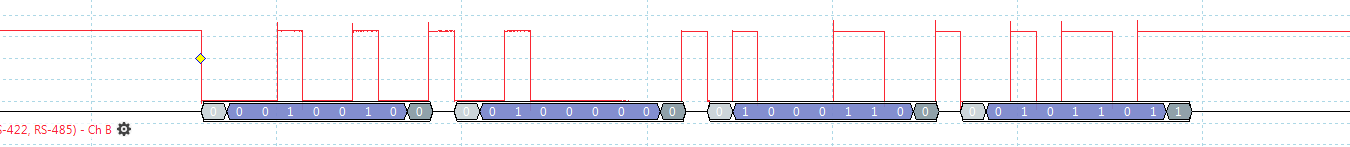
I am passing an array of uint8_t values. Only 4 bytes. The bytes are getting transmitted via the TX pin as expected, but only 7 bits per byte are transmitted. (see tx_8_bits_no_parity image).
So I got into the F429xx datasheet (
) and on page 994 the Table 146 clearly states that when the bits M (length = 8bits) and PCE (parity = None) are reset, the UART frame will be: Start Bit, 8 data bits, Stop Bit.Why is MCU sending only 7 bits when no parity is enabled? So I decided to enable parity in CubeMX and set it to Even.
However, the parity bit just takes up one of the 8 bits, making the data only 6 bits! (see tx_8_bits_even_parity image).
The same table 146, clearly states that the MCU should be sending 7 Data bits and not 6.
How can this be? Am I missing something? I am only trying to send 8 bits of data (0x00 - 0xFF) without parity.
Any advise would be appreciated.
Thanks.
#uart #bug #f4 #cube-mx #halSolved! Go to Solution.
Labels:
1 ACCEPTED SOLUTION
Accepted Solutions
Options
- Mark as New
- Bookmark
- Subscribe
- Mute
- Subscribe to RSS Feed
- Permalink
- Email to a Friend
- Report Inappropriate Content
2017-08-01 06:34 AM
Posted on August 01, 2017 at 13:34
That decoder was written by somebody who does not quite understand how UART works.
The stopbit is transmitted as a whole bit, but it is received by sampling it in its middle (usually with the 3x oversampling). Start bit falling edge detection commences immediately after that. The consequence is, that even if the transmitter's actual bit time is slightly above the receiver's (here: your 'detector''s) expected bit time, the receiver still works flawlessly.
JW
12 REPLIES 12
Options
- Mark as New
- Bookmark
- Subscribe
- Mute
- Subscribe to RSS Feed
- Permalink
- Email to a Friend
- Report Inappropriate Content
2017-07-31 03:03 PM
Posted on August 01, 2017 at 00:03
I have found that STM32CubeMX (or at least recent versions) default to 7 bits, no parity, 115200 baud on the UART/USARTs in the generated code. I make sure I set, or at least check, all of the configuration options in the tool before generating code for a project.
This may not be your case, but it is something to be aware of.
Options
- Mark as New
- Bookmark
- Subscribe
- Mute
- Subscribe to RSS Feed
- Permalink
- Email to a Friend
- Report Inappropriate Content
2017-08-01 03:11 AM
Posted on August 01, 2017 at 10:11
Daniel, thank you for your reply. The default settings are fine. However, what the MCU is outputting on a UART TX line with these settings (defaults from your post) are not what is described in the datasheet (
).There is no valid UART/USART frame with 7 data bits and no parity (please see image).
The default configuration in the CubeMX (8-bit Word (M bit = 0) + No Parity (PCE = 0) ) should produce an 8 bit data length, not 7.
Kind regards,
Dainius
Options
- Mark as New
- Bookmark
- Subscribe
- Mute
- Subscribe to RSS Feed
- Permalink
- Email to a Friend
- Report Inappropriate Content
2017-08-01 03:15 AM
Posted on August 01, 2017 at 12:15
It's your decoding (program? scope? LA?) which is flawed, not the UART. There are clearly 1 start bit, 8 data bits and 1 stop bit on the tx_8_bits_no_parity.PNG
JW
Options
- Mark as New
- Bookmark
- Subscribe
- Mute
- Subscribe to RSS Feed
- Permalink
- Email to a Friend
- Report Inappropriate Content
2017-08-01 03:27 AM
Posted on August 01, 2017 at 12:27
Hello!
I use UART 2 8n1 configuration on 32f429zi with not any issue.
I use last versions CUBEMX and software pack. and windows 10.
Is it posible to post the .IOC file to help the community reproduce the problem and to solve it?
Check at Run time the Control registers of UART for consistency .
Options
- Mark as New
- Bookmark
- Subscribe
- Mute
- Subscribe to RSS Feed
- Permalink
- Email to a Friend
- Report Inappropriate Content
2017-08-01 04:00 AM
Posted on August 01, 2017 at 11:00
In addition I have tried the same UART setup ( 8-bit Word Length, No parity, 115200 baud - CubeMX defaults ) on a STM32F401RE Nulceo board and guess what, the MCU does output 8 bits of data.
The same exact configuration on a STM32F429ZI Nucleo board outputs only 7 bits of data.
Options
- Mark as New
- Bookmark
- Subscribe
- Mute
- Subscribe to RSS Feed
- Permalink
- Email to a Friend
- Report Inappropriate Content
2017-08-01 05:41 AM
Posted on August 01, 2017 at 12:41
Hi Vengelis,
I have attached the .IOC file. My apologies, I should have thought about it earlier. I am running the Linux Version of Cube MX.
I captured the CRx registers for UART2. The values were:
- CR1 = 8492 (dec), bit set were -> RE, TE, RXNEIE, PEIE, UE
- CR2 = 0
- CR3 = 1 (dec) , bit set were -> EIE.
Options
- Mark as New
- Bookmark
- Subscribe
- Mute
- Subscribe to RSS Feed
- Permalink
- Email to a Friend
- Report Inappropriate Content
2017-08-01 06:03 AM
Posted on August 01, 2017 at 13:03


Brought my Paint skills into action.
Data transmitted is (decimal):
[0] = 36
[1] = 2
[2] = 49
[3] = counter, 0 - 255. Due to being only 7 bits, rolls over at 127, but in the software the counter keep going until 255.
The only way I can decode the data if I remove the Stop bit from the decoder's configuration and set data length to 8 bits. Then it works fine.
However, my USART2 peripheral configuration does contain a 1 Stop bit.
Options
- Mark as New
- Bookmark
- Subscribe
- Mute
- Subscribe to RSS Feed
- Permalink
- Email to a Friend
- Report Inappropriate Content
2017-08-01 06:11 AM
Posted on August 01, 2017 at 13:11
Stop bit is high.
There is no reason to wait after stop bit, the next start bit proceeds immediately.
JW
Options
- Mark as New
- Bookmark
- Subscribe
- Mute
- Subscribe to RSS Feed
- Permalink
- Email to a Friend
- Report Inappropriate Content
2017-08-01 06:11 AM
Posted on August 01, 2017 at 13:11 
Your settings are right!
I tested it on my 429disco board and Teraterm.
take a look at this figure from RM .(M=0 means 8N1)
So .. There is not any error.. Check the polarity of stop bit..
Waclawek.Jan
has right.Check your Logic analyser or capture equipment you use.
Related Content
- Reinitialization of UART and ADC in STM32CubeProgrammer (MCUs)
- STM32L432 UART receive IRQ handler unable to created by Cube in STM32CubeMX (MCUs)
- CubeMX Register Callback does not work / is missing for SDADC in STM32CubeMX (MCUs)
- UART cosfiguration directly with registers, NUCLEO-H563ZI board in STM32CubeIDE (MCUs)
- Readout external ADC by SPI doesn't work correctly in STM32CubeIDE (MCUs)