Turn on suggestions
Auto-suggest helps you quickly narrow down your search results by suggesting possible matches as you type.
Showing results for
- STMicroelectronics Community
- STM32 MCUs
- STM32 MCUs products
- STM32f7 - ripples on 5.0V supply
Options
- Subscribe to RSS Feed
- Mark Topic as New
- Mark Topic as Read
- Float this Topic for Current User
- Bookmark
- Subscribe
- Mute
- Printer Friendly Page
STM32f7 - ripples on 5.0V supply
Options
- Mark as New
- Bookmark
- Subscribe
- Mute
- Subscribe to RSS Feed
- Permalink
- Email to a Friend
- Report Inappropriate Content
2017-09-18 09:20 AM
Posted on September 18, 2017 at 18:20
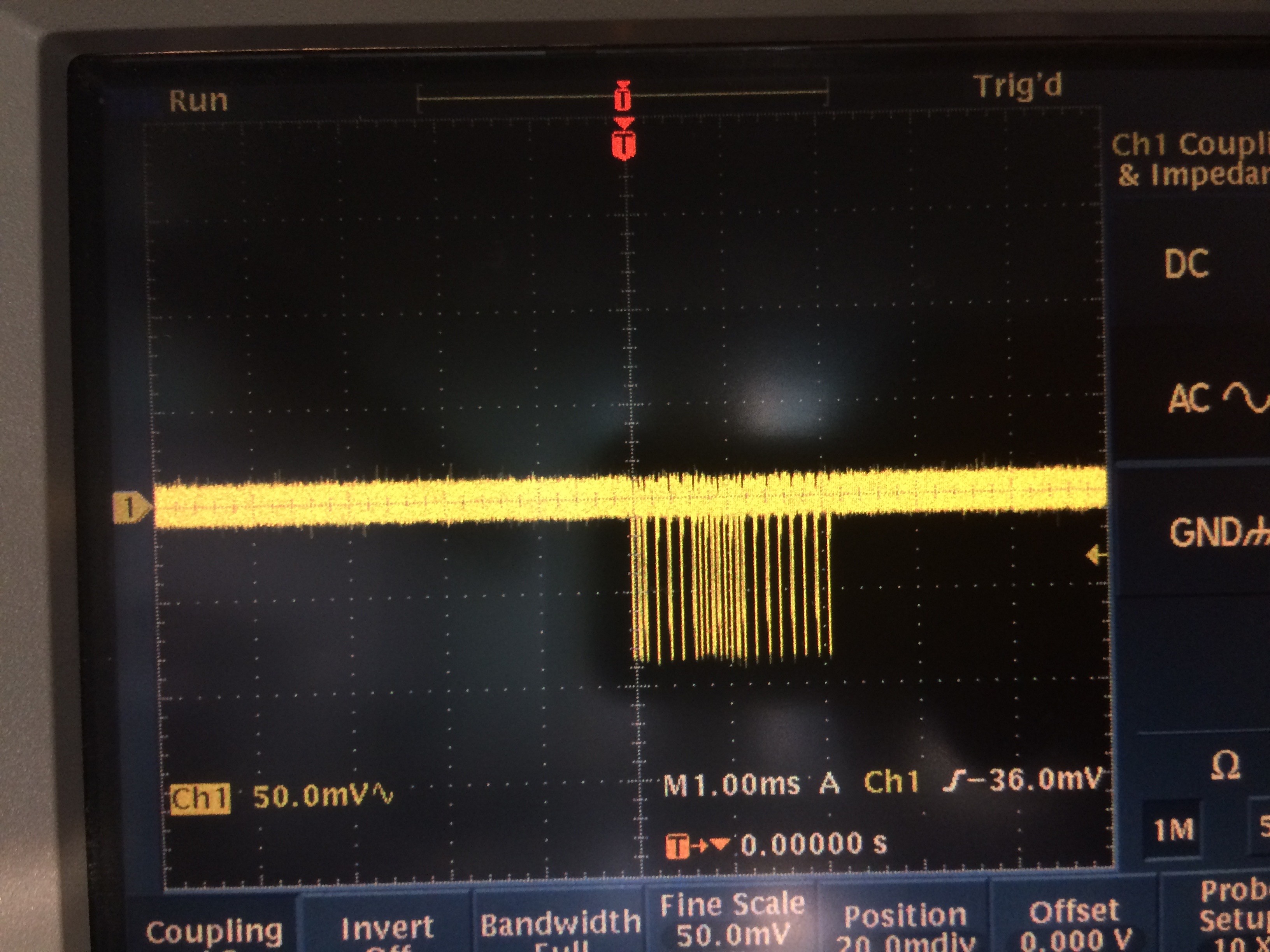
I have noticed that STM32F7 microcontroller generates a digital noise (see the figures. It is not from transmission lines and bursts are repeating every 16ms) on the 5.0V supply voltage.
I have observed this using both Discovery and Nucleo boards.
I have seen this using external power supply and the power over USB.
I have also tried different sample codes. It actually does not matter what code you run, because even before I start the code in my debugger, the ripples can be observed. The only time, I do not see the ripples, is when the microcontroller is kept in reset, or when I remove a jumper to power it down.
I have also noticed that, after couple of resets, the noise sometimes disappear. It comes back if I reset again.
Anyone else who has observed this issue? Any thoughts?
#ripples #noise #stm32f7 #power-supply
Labels:
- Labels:
-
STM32F7 Series
11 REPLIES 11
Options
- Mark as New
- Bookmark
- Subscribe
- Mute
- Subscribe to RSS Feed
- Permalink
- Email to a Friend
- Report Inappropriate Content
2017-09-18 10:21 AM
Posted on September 18, 2017 at 19:21
There is something else running in your board. Some HW counters for instance. Have you measured the 3.3V power supply of the CPU. That is critical. If you mean by 5V the supply from USB, it could be anything. I think minimum is 4.4V or so and cheap low quality cables can make it even worse.
Options
- Mark as New
- Bookmark
- Subscribe
- Mute
- Subscribe to RSS Feed
- Permalink
- Email to a Friend
- Report Inappropriate Content
2017-09-18 11:26 AM
Posted on September 18, 2017 at 20:26
First, thank you for your response
Michael.Lei
.The 3.3V is generated from the 5.0V on these boards, by means of a voltage regulator. So the 3.3V also suffers from the ripples.
As I mentioned in my first post, I have observed this, when using USB supply, external independent supply, and even a battery. I have also tried normal and good quality cables. Nothing helps. It is moreplausible that a component on theboard or the microcontoller itselfgenerating those digital pulses. I have not been able to figure out the source yet.Options
- Mark as New
- Bookmark
- Subscribe
- Mute
- Subscribe to RSS Feed
- Permalink
- Email to a Friend
- Report Inappropriate Content
2017-11-26 12:17 PM
Posted on November 26, 2017 at 20:17
is the same with turning off most peripherals ?
Options
- Mark as New
- Bookmark
- Subscribe
- Mute
- Subscribe to RSS Feed
- Permalink
- Email to a Friend
- Report Inappropriate Content
2017-11-26 12:56 PM
Posted on November 26, 2017 at 20:56
Digital circuits make noise in their power supplies, because their current consumption is not smooth but varies in time.
Options
- Mark as New
- Bookmark
- Subscribe
- Mute
- Subscribe to RSS Feed
- Permalink
- Email to a Friend
- Report Inappropriate Content
2017-11-27 05:43 AM
Posted on November 27, 2017 at 13:43
F7 can't generate noise on 5V supply rail which is behind regulator, because F7 consumes power from 3.3V rail (and regulates it even more by means of internal LDO). I suggest that culprit is in some other circuitry. May be decoupling issues. May be its your oscilloscope probe is glitching. Could be anything, but i doubt that MCU is one to blame
Options
- Mark as New
- Bookmark
- Subscribe
- Mute
- Subscribe to RSS Feed
- Permalink
- Email to a Friend
- Report Inappropriate Content
2017-11-27 06:37 PM
Posted on November 28, 2017 at 03:37
I checked my homemade board, I have a 7805 (K7805-1000R3) style switcher on board showing 400mV spikes at 100KHz.
I have two 2A ferrites in series with those 2 power lines. (5V and Gnd)
I put caps everywhere I can, usually a 1uF and a 0.1uF where requested by the datasheets. the bigger the better. 0805's are easy to work with.
Under reset, the noise is from the power supply, 400mV spikes before and a neat 100mV after the ferrites.
release the reset and run my canbus/ethernet thing, 400mV noise before and a messy 100mV after the ferrites.
I drop the rail from 5V down through two diodes, approx 1.1V drop just to remove the heat from the linear reg.
I run the linear 3V reg from those diodes. AP2114H-3.3TRG1
Noise on processor pins:
actually, if I put the scope leads to either side on any cap on the processor, it is approx 10mV noise in reset or not.
There are no repetitive spikes on the processor pins..above 20mV at any frequency running or not.
EDIT: I don't have DRAM running on my board. what is the refresh frequency ?
the DRAM specs say there is a noisy path to pay special attention to.Options
- Mark as New
- Bookmark
- Subscribe
- Mute
- Subscribe to RSS Feed
- Permalink
- Email to a Friend
- Report Inappropriate Content
2017-11-27 07:41 PM
Posted on November 28, 2017 at 03:41
it is very important to put the ground probe on the relative ground.
primary switch mode noise is on the ground wire.
if you connect the scope ground here, all you will see is the switching noise.
Options
- Mark as New
- Bookmark
- Subscribe
- Mute
- Subscribe to RSS Feed
- Permalink
- Email to a Friend
- Report Inappropriate Content
2017-11-28 04:21 AM
Posted on November 28, 2017 at 12:21
yes, that too. And its always better to have solid ground layer or, at least, ground polygons on both sides of 2-layered board, tightly tied together with lots of vias: low impedance for return currents is the key to success
Options
- Mark as New
- Bookmark
- Subscribe
- Mute
- Subscribe to RSS Feed
- Permalink
- Email to a Friend
- Report Inappropriate Content
2017-11-28 02:08 PM
Posted on November 28, 2017 at 23:08
Modern digital oscilloscopes can detect a signal with a frequency of 100 MHz or higher. But this does not mean the use of old measuring methods with grounding by a long wire. On this loop, you can catch an external radio signal, you can enhance the interference from the source, you can introduce significant distortion in the measured circuit. A long wire is always inductance. At frequencies above 100 MHz, this becomes noticeable.
Solution.
In the kit with the measured oscilloscope probe should be small springs, which are worn on the metal part of the probe. It looks like a spring, it is dressed like a spring, but it works like a point of contact of the earth. Having very small dimensions, and very close ground contact - the minimum contact inductance is obtained. External interference disappears. You measure a useful signal in differential mode. A very long wire of the probe itself will play the role of a large inductor (for such a frequency). As a result, the useful signal and the ground point will have synchronous oscillations. And on the oscilloscope connector will come a signal shot at the point of contact.
Related Content
- STM32 Power supply ripple voltage in STM32 MCUs products
- Code won't run after power cycling when debugger isn't connected in STM32 MCUs products
- Servo not working with STM32F767Zi in STM32CubeMX (MCUs)
- STM32F7 supply issues in STM32 MCUs products
- STM32WB55: Power supply ripple/pulsation causing BLE TX to fail in STM32 MCUs Wireless