Turn on suggestions
Auto-suggest helps you quickly narrow down your search results by suggesting possible matches as you type.
Showing results for
- STMicroelectronics Community
- STM32 MCUs
- STM32 MCUs products
- STM32F103 Timer Interrupt Issue
Options
- Subscribe to RSS Feed
- Mark Topic as New
- Mark Topic as Read
- Float this Topic for Current User
- Bookmark
- Subscribe
- Mute
- Printer Friendly Page
STM32F103 Timer Interrupt Issue
Options
- Mark as New
- Bookmark
- Subscribe
- Mute
- Subscribe to RSS Feed
- Permalink
- Email to a Friend
- Report Inappropriate Content
2018-04-24 05:15 AM
Posted on April 24, 2018 at 14:15
Hello, I am using a stm32f103c8 micro-controller. I am using STLINK/V2 for debugging in MDK-ARM v5 environment.
I have programmed TIMER 3 in simple PWM mode using code from Standard Peripheral Library (SPL) example. The code is attached below for reference:
TIM_TimeBaseInitTypeDef TIM_TimeBaseStructure;
TIM_OCInitTypeDef TIM_OCInitStructure;uint16_t CCR1_Val = 333;/* Compute the prescaler value */
PrescalerValue = (uint16_t) (SystemCoreClock / 24000000) - 1; /* Time base configuration */ TIM_TimeBaseStructure.TIM_Period = 665; TIM_TimeBaseStructure.TIM_Prescaler = PrescalerValue; TIM_TimeBaseStructure.TIM_ClockDivision = 0; TIM_TimeBaseStructure.TIM_CounterMode = TIM_CounterMode_Up;TIM_TimeBaseInit(TIM3, &TIM_TimeBaseStructure);
/* PWM1 Mode configuration: Channel1 */
TIM_OCInitStructure.TIM_OCMode = TIM_OCMode_PWM1; TIM_OCInitStructure.TIM_OutputState = TIM_OutputState_Enable; TIM_OCInitStructure.TIM_Pulse = CCR1_Val; TIM_OCInitStructure.TIM_OCPolarity = TIM_OCPolarity_High;TIM_OC1Init(TIM3, &TIM_OCInitStructure);
TIM_OC1PreloadConfig(TIM3, TIM_OCPreload_Enable);
TIM_ARRPreloadConfig(TIM3, ENABLE);/* TIM3 enable counter */
TIM_Cmd(TIM3, ENABLE); TIM_ITConfig(TIM3,TIM_IT_Update,ENABLE);NVIC_InitStructure.NVIC_IRQChannel = TIM3_IRQn;
NVIC_InitStructure.NVIC_IRQChannelPreemptionPriority = 0; NVIC_InitStructure.NVIC_IRQChannelSubPriority = 0; NVIC_InitStructure.NVIC_IRQChannelCmd = ENABLE; NVIC_Init(&NVIC_InitStructure);Basically this software simply configures the TIMER 3 to produce a square wave with 50% duty cycle. Now I have enabled Timer Update Interrupt as well because I want interrupt every time counter overflows. The Timer ISR is given below:
void TIM3_IRQHandler(void)
{ if(TIM_GetITStatus(TIM3, TIM_IT_Update) != RESET) { TIM_ClearITPendingBit (TIM3,TIM_IT_Update); GPIO_WriteBit(GPIOC, GPIO_Pin_14, (BitAction)(1 - GPIO_ReadOutputDataBit(GPIOC, GPIO_Pin_14))); }}The ISR simply toggles a GPIO pin which is connected to oscilloscope for viewing.
Now, I understand that every time the counter overflows, the interrupt
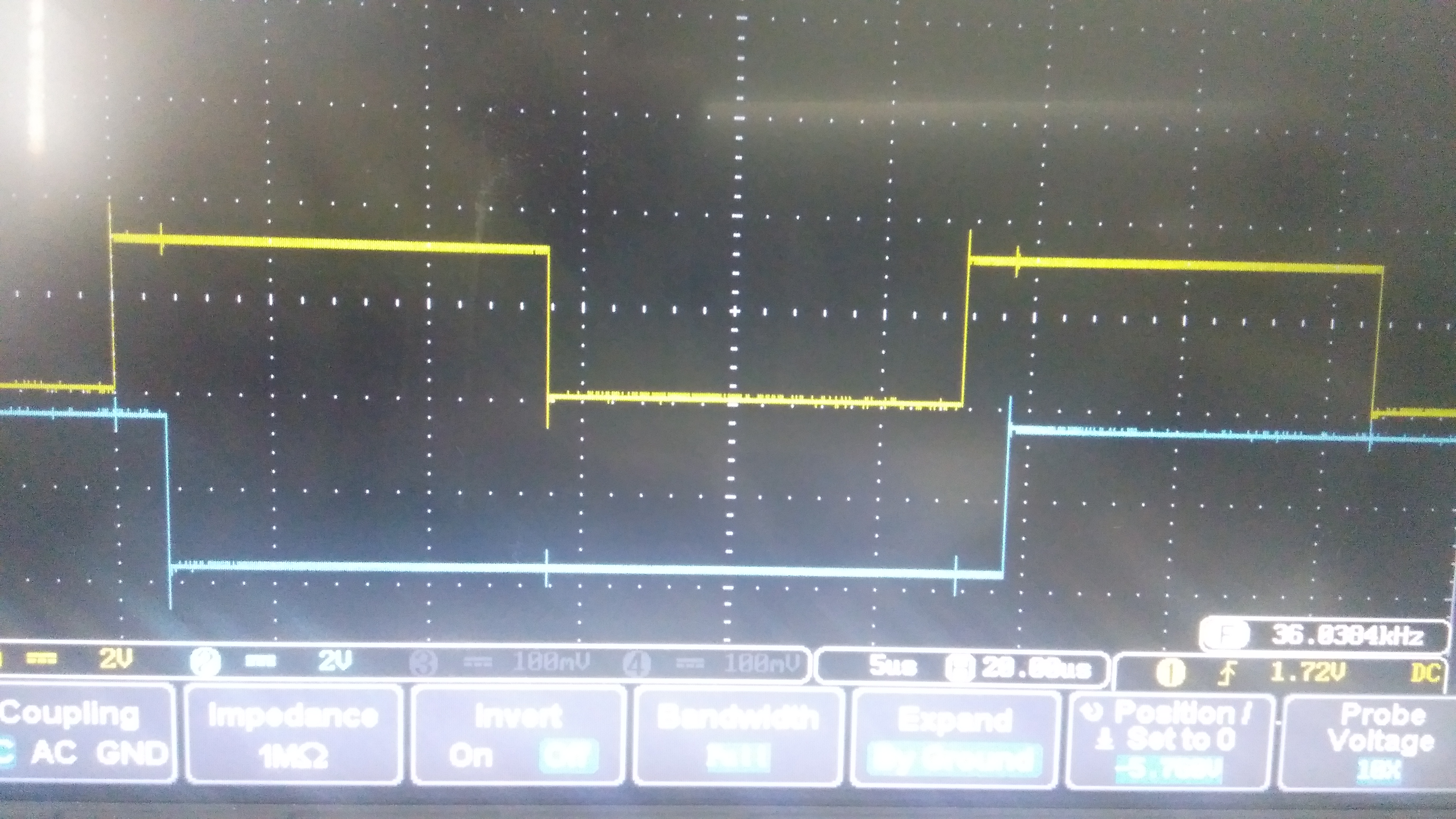
TIM_IT_Update should fire and the ISR should execute immediately. The ISR above simply toggles an IO, so the IO pin should change almost immediately after interrupt. However, I have achieved the result as shown in picture attached:
In image, the yellow trace is the PWM output of timer 3 and the blue trace is the GPIO being toggled in ISR. The issue I have is that there seems to be a delay between two wave shapes. The delay is almost 1us. This implies that either the ISR is being executed with a delay, i.e. the interrupt doesn't fire immediately after counter overflow, or there is some delay in the ISR itself.
The SystemCoreClock is 72 MHz. So my guess is that the interrupt is being fired with a delay. I have also tried disabling Systick interrupts. The result remains the same. I will appreciate any help in this regard. Thanks.
#stm32f103-interrupt
Labels:
- Labels:
-
STM32F1 Series
9 REPLIES 9
Options
- Mark as New
- Bookmark
- Subscribe
- Mute
- Subscribe to RSS Feed
- Permalink
- Email to a Friend
- Report Inappropriate Content
2018-04-24 07:26 AM
Posted on April 24, 2018 at 16:26
The ISR above simply toggles an IO, so the IO pin should change almost immediately after interrupt.
The question is, what is 'almost immediately' and what is your expectation based on.According to your DSO pic there is almost 2us delay lets say 1.7us (if I'm reading your timebase correctly) At 72MHz thats approximately 122 instruction cycles.
I would say that the way you are toggling the pin has a lot to do with the delay - first reading the current state then writing out (1-current_state) using SPL functions is not the most efficient way to do it. Try another function such as
LL_GPIO_TogglePin or even a direct write to the BSRR/BRR registers for the GPIO port eg.
GPIO_Port->BSRR |= (1 << YOUR_PIN); // set GPIO pin
See if that makes a difference.
Options
- Mark as New
- Bookmark
- Subscribe
- Mute
- Subscribe to RSS Feed
- Permalink
- Email to a Friend
- Report Inappropriate Content
2018-04-24 07:37 AM
Posted on April 24, 2018 at 16:37
1uS is not so bad,
you can imagine that the PWM is a hardware signal developed from AND gates and the Timer Counter itself.
another hardware function is to trigger the interrupt.
these will happen at the same instant.
@ 72MHz you only get 72 cycles in 1uS.
there is a slight delay to get to the first instruction of the ISR, that could be 2-7 clocks there with no other DMA or Interrupts
then you are running this code bits:
if // 1 clock cycle
(TIM_GetITStatus(TIM3, TIM_IT_Update) != RESET) // 20-30 clocks
{ TIM_ClearITPendingBit (TIM3,TIM_IT_Update); // 10-20 clocksand some more here just before the pin is actually toggled..
// 5-10 clocks
GPIO_WriteBit(GPIOC, GPIO_Pin_14, (BitAction)(1 - GPIO_ReadOutputDataBit(GPIOC, GPIO_Pin_14)));that's about 70 clock cycles delay from the hardware interrupt to the software response: toggle pin.
Options
- Mark as New
- Bookmark
- Subscribe
- Mute
- Subscribe to RSS Feed
- Permalink
- Email to a Friend
- Report Inappropriate Content
2018-04-24 11:17 AM
Posted on April 24, 2018 at 18:17
This is really helpful. Thanks alot
Options
- Mark as New
- Bookmark
- Subscribe
- Mute
- Subscribe to RSS Feed
- Permalink
- Email to a Friend
- Report Inappropriate Content
2018-04-24 11:17 AM
Posted on April 24, 2018 at 18:17
I did try this approach. However, I will try again with your code. Thanks for help
Options
- Mark as New
- Bookmark
- Subscribe
- Mute
- Subscribe to RSS Feed
- Permalink
- Email to a Friend
- Report Inappropriate Content
2018-04-24 11:05 PM
Posted on April 25, 2018 at 06:05
You're welcome.
Options
- Mark as New
- Bookmark
- Subscribe
- Mute
- Subscribe to RSS Feed
- Permalink
- Email to a Friend
- Report Inappropriate Content
2018-04-24 11:22 PM
Posted on April 25, 2018 at 06:22
PS: I'm assuming you initialized the GPIO pin as output and connected to hi-speed clock, right ?
Options
- Mark as New
- Bookmark
- Subscribe
- Mute
- Subscribe to RSS Feed
- Permalink
- Email to a Friend
- Report Inappropriate Content
2018-04-25 04:09 AM
Posted on April 25, 2018 at 13:09
1us #= 72 ticks. That sounds a little excessive but not impossible, between your isr overhead plus execution.
If you operate on the SR or ODR registers you may be able to get that down to 30 ticks.
Options
- Mark as New
- Bookmark
- Subscribe
- Mute
- Subscribe to RSS Feed
- Permalink
- Email to a Friend
- Report Inappropriate Content
2018-04-25 04:36 AM
Posted on April 25, 2018 at 11:36
Yes I did that. I have come to the same understanding as explained by yourself and Mr. T J.
Options
- Mark as New
- Bookmark
- Subscribe
- Mute
- Subscribe to RSS Feed
- Permalink
- Email to a Friend
- Report Inappropriate Content
2018-04-25 06:56 PM
Posted on April 26, 2018 at 01:56
@dhenry, what is the correct calculation of the number of ticks in a uSec ?
Related Content
- Reading ADC Channel using DMA, While Loop not Executing. Debug stuck at HAL_DMA_IRQHandler in STM32 MCUs products
- Interrupt triggering twice - check for interrupt clear latency issue does not work in STM32 MCUs products
- STM32G491 FDCAN: Issue with error counters in STM32 MCUs products
- Timer input capture interrupt fires over and over - Not a late flag reset issue (probably) in STM32 MCUs products
- High current consumption in Stop Mode on STM32U575 DEV Kit and Custom Board in STM32 MCUs products